Fab9 EFR turbo kit install
My 2022 plans of going from forced induction to naturally aspirated did not last long. The Stage 2 cams did not give me the performance I had hoped for. I would say my tune was 90% dialed in but only managed a 1.41,3 @ Rudskogen (goal sub 1.40 NA). It also came with rougher idle, less street friendly and most of the gains >7K which is not a good place for the 100mm stroke 1.51 rod ratio L5.
13 years ago i ran a fully built 04 MSM with a GT3071 @ 1.8 bar. Fun but hard to get control the power and get good consistent lap times so I spent the next 10 years playing with superchargers. Long story short, I decided to give turbo supercharging another go and ordered the Fab9Tuning EFR V-Band Bottom Mount Turbo Kit late 2022. Hopefully new turbo tech, better EMS and more displacement will make power management and delivery better.
<TL/DR>
What I like:
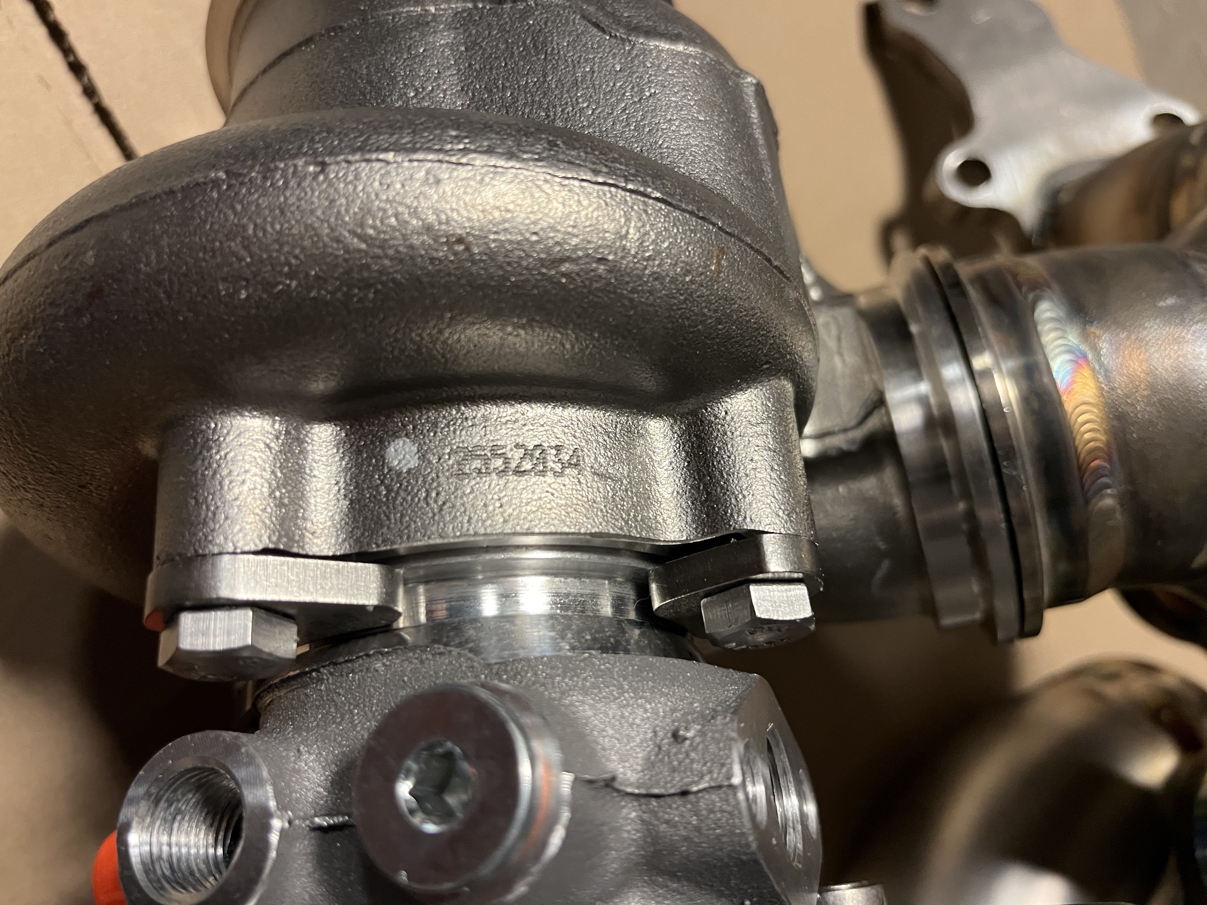
- Fully v-band turbo inlet and outlet. No stretched turbo bolts or warped flanges
- Low mount for optimal flow,layout,stealthiness and heat management
- Very high quality hard parts and fabrication
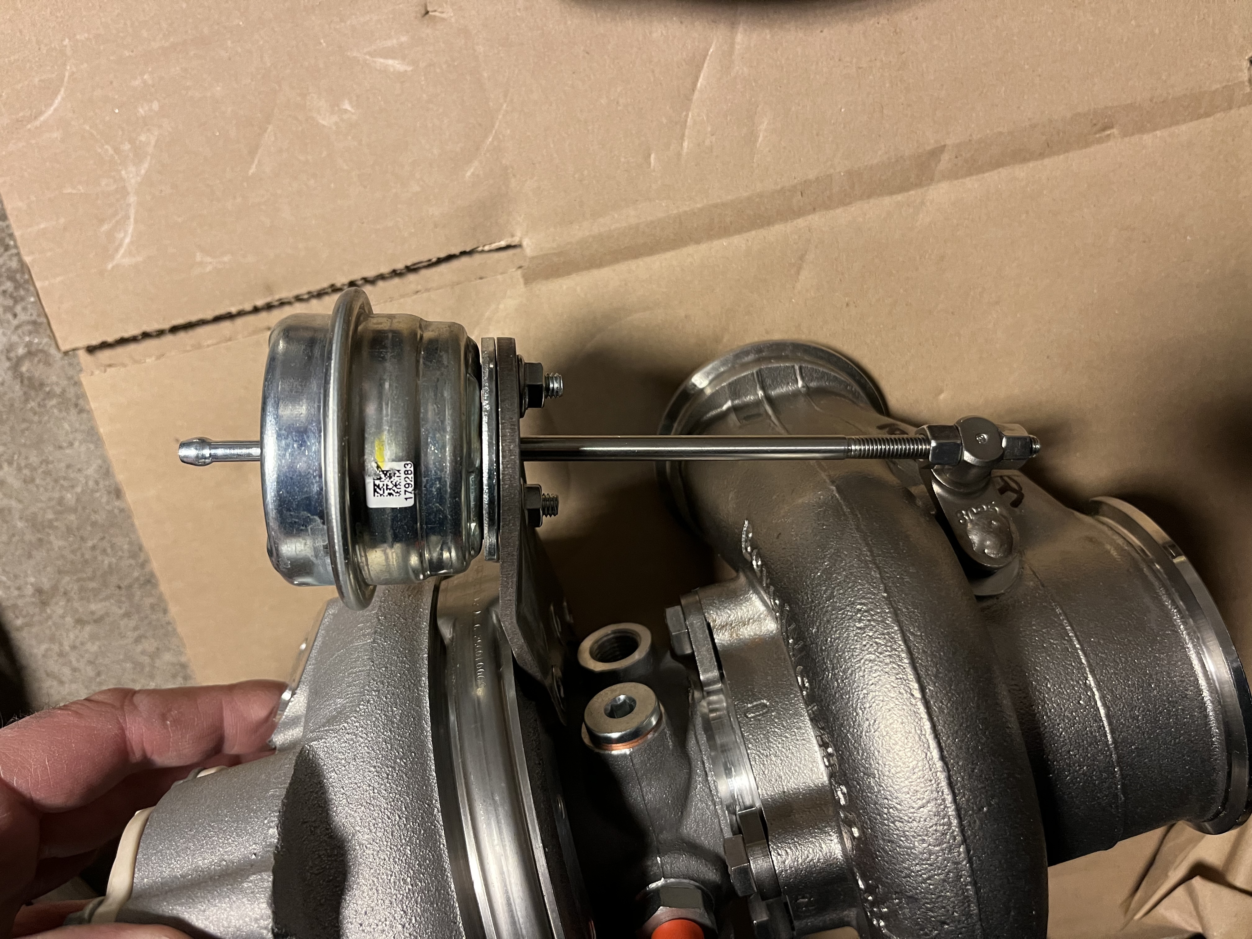
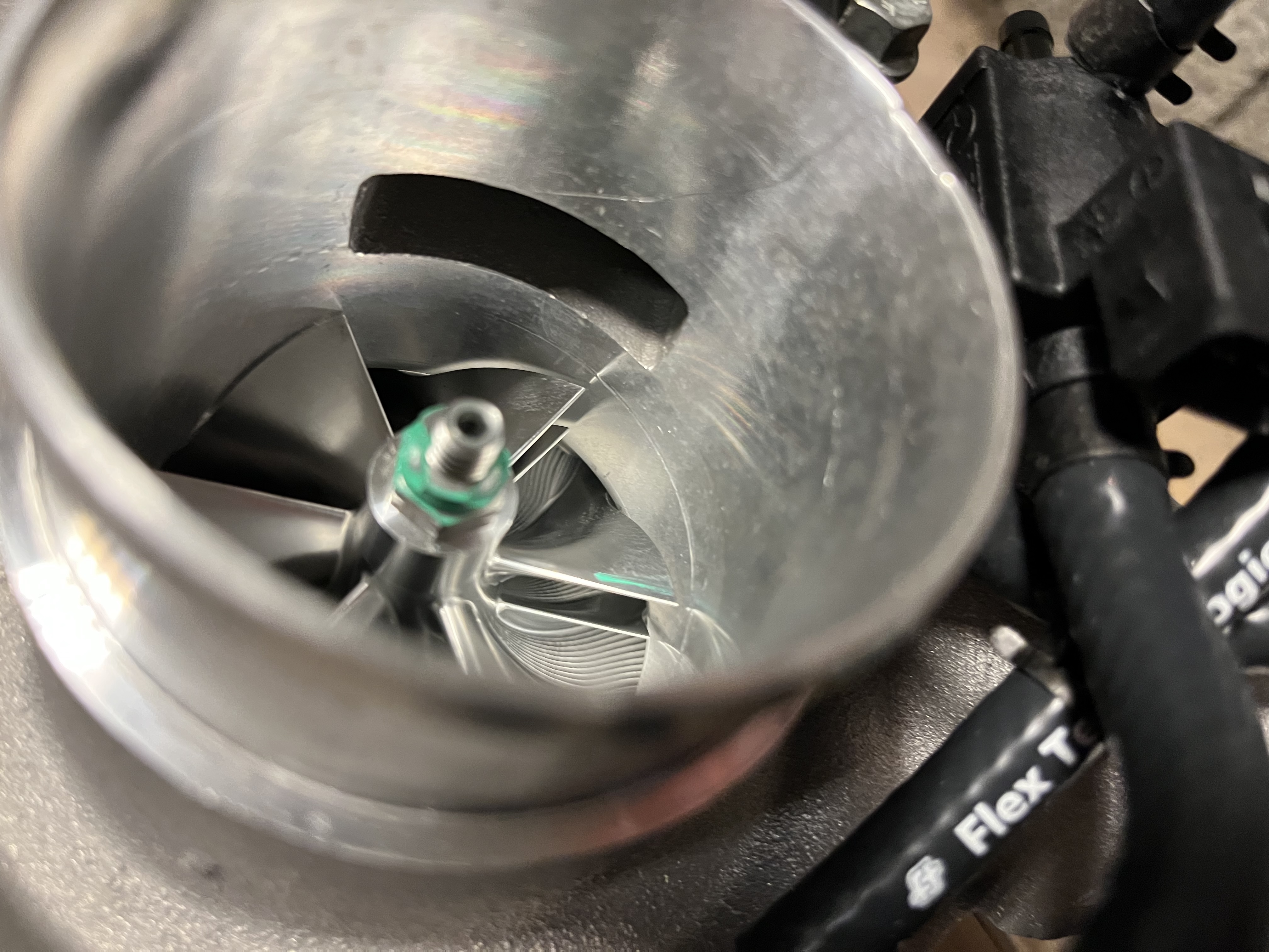
- Modern compact turbo with high flow internal WG, integrated BOV and solenoid valve
Could be better:
- Involving install
- Made to order, six months until I got all the parts.
- Limited installation instructions
But compared to the other alternatives out there this is way ahead of the competition imho.
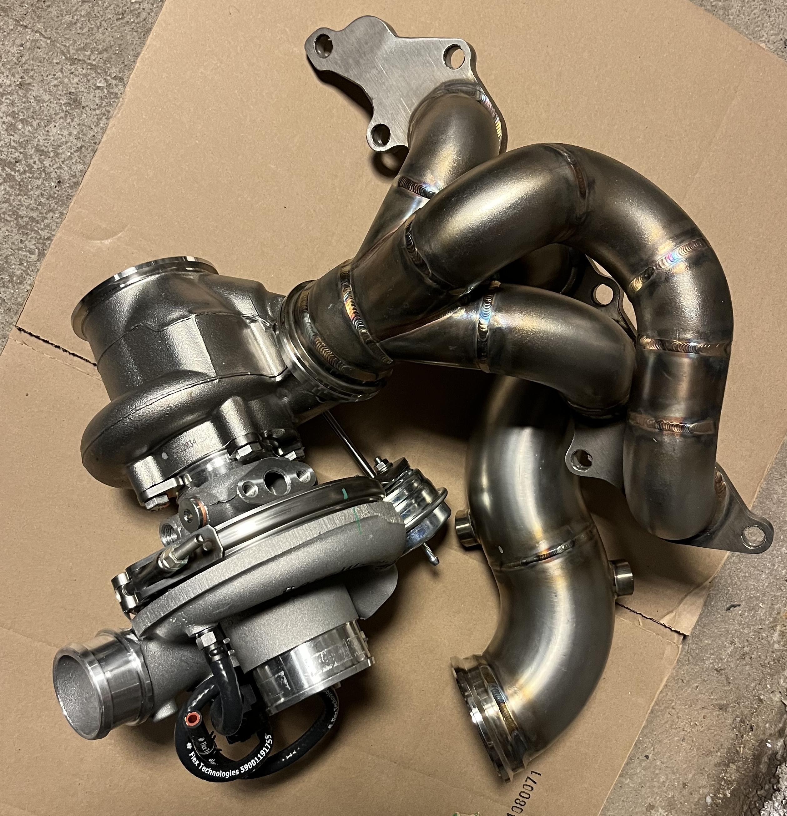
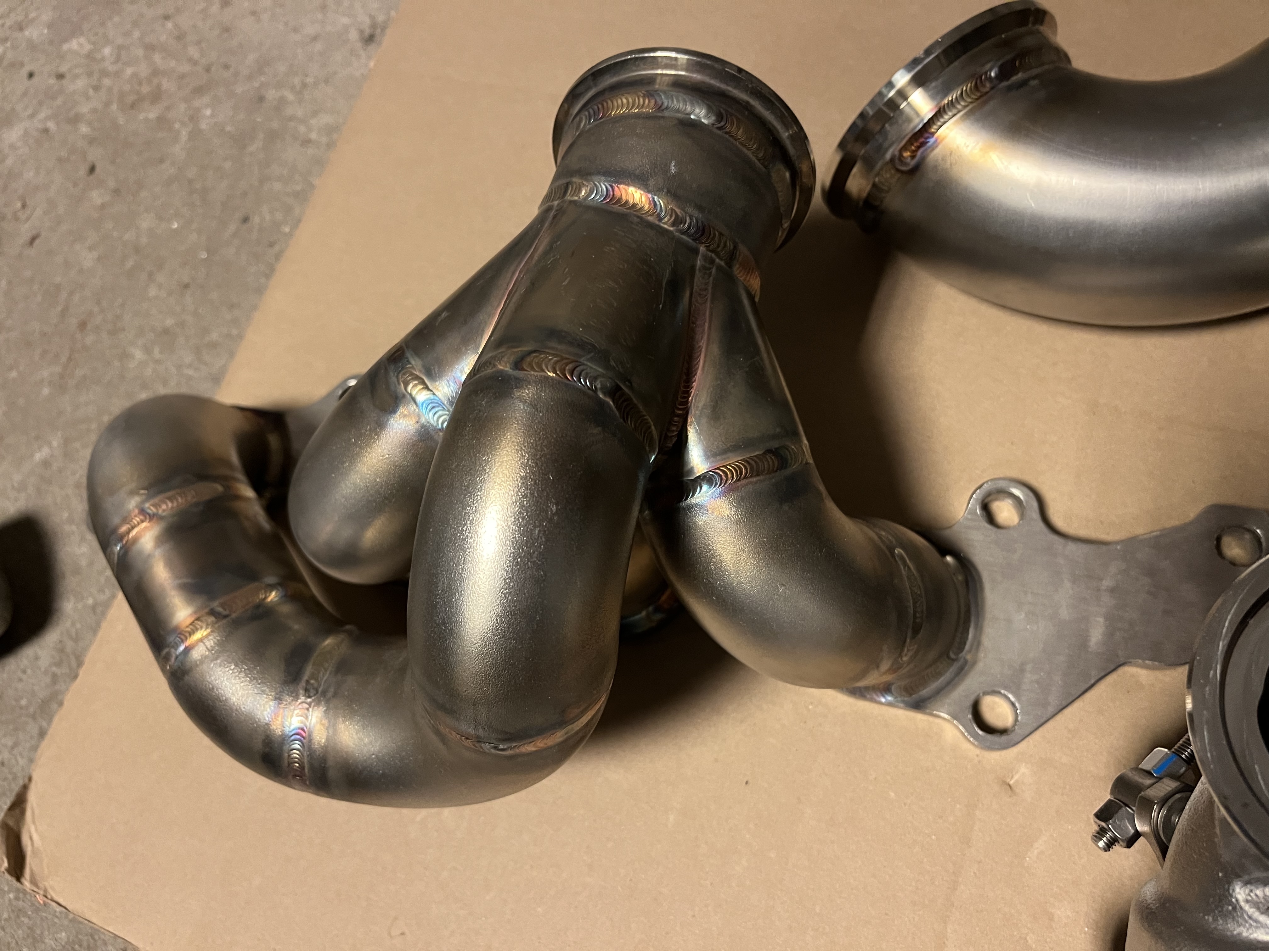
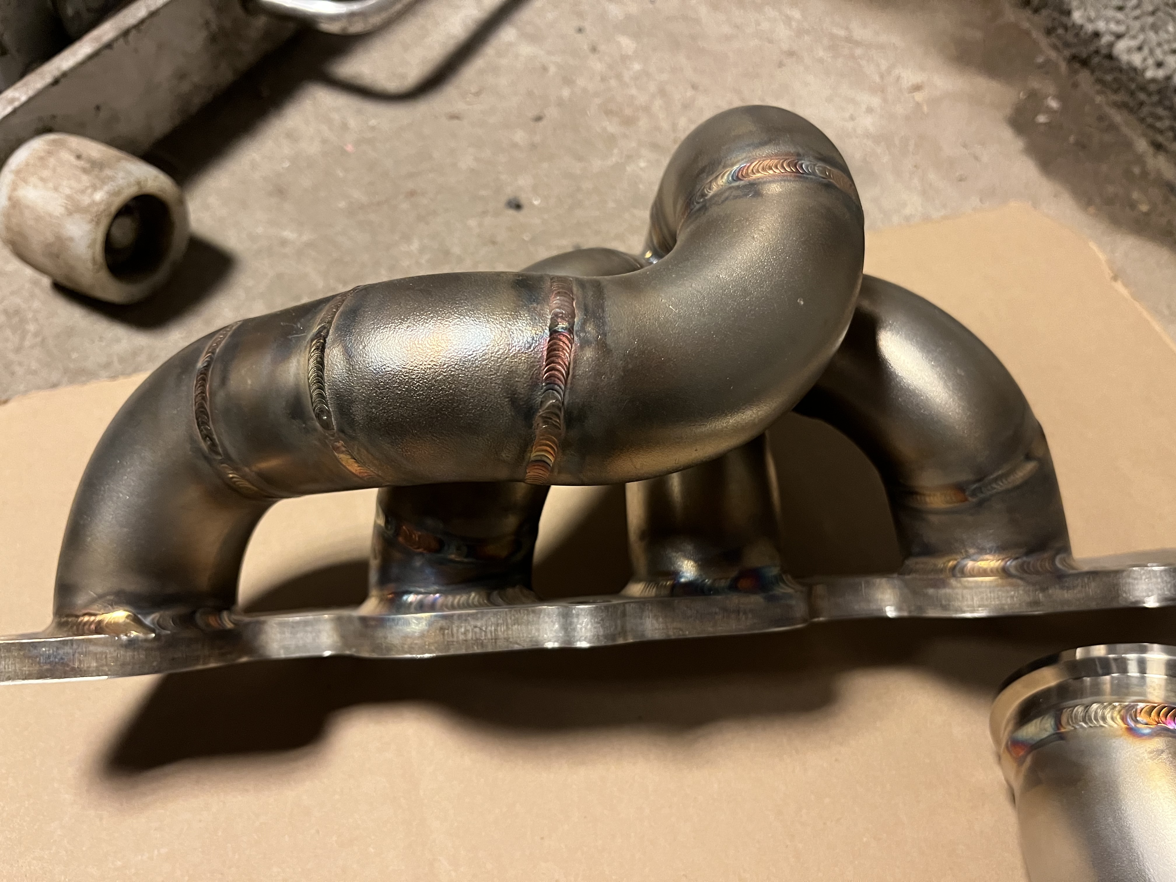
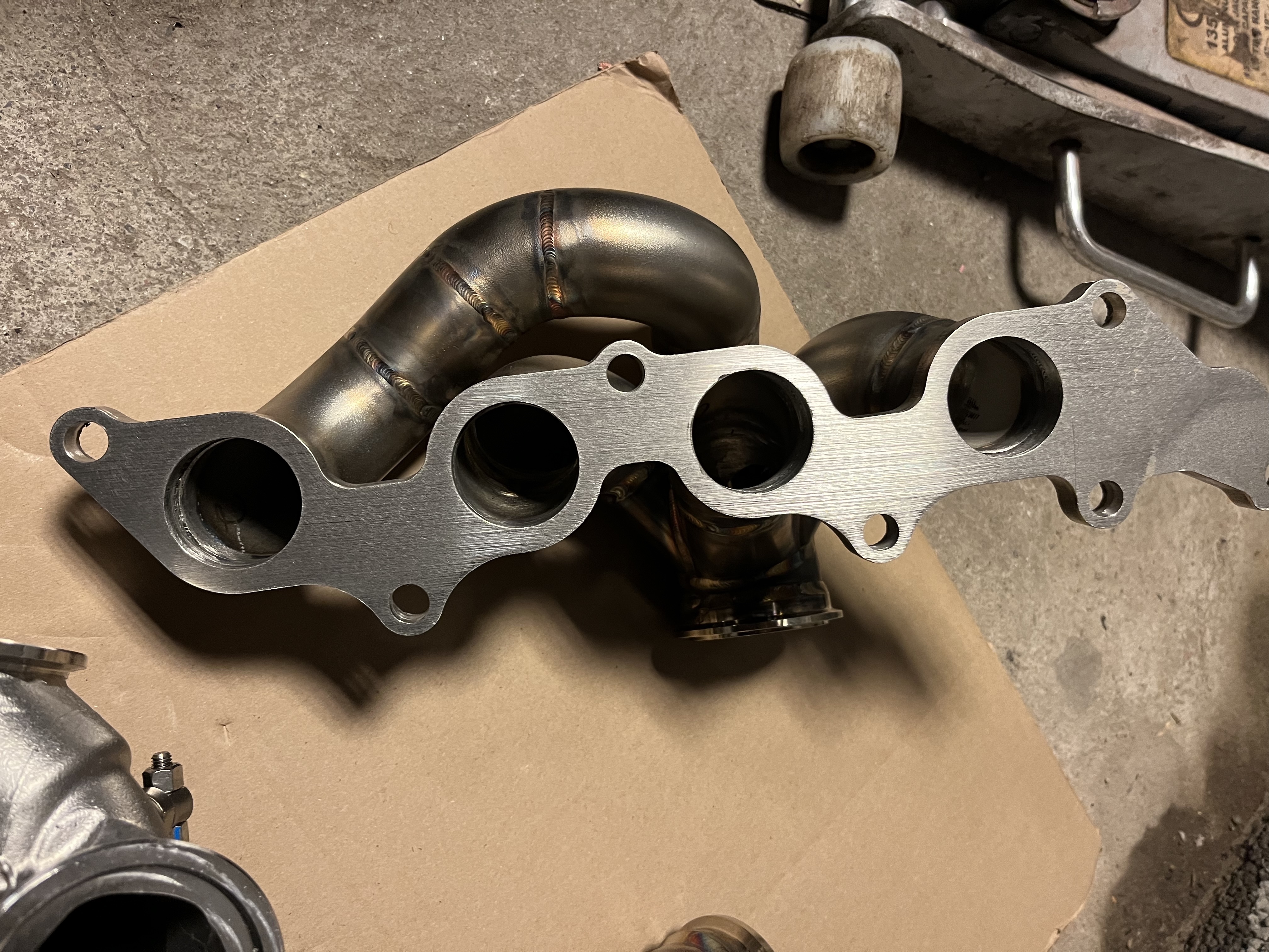
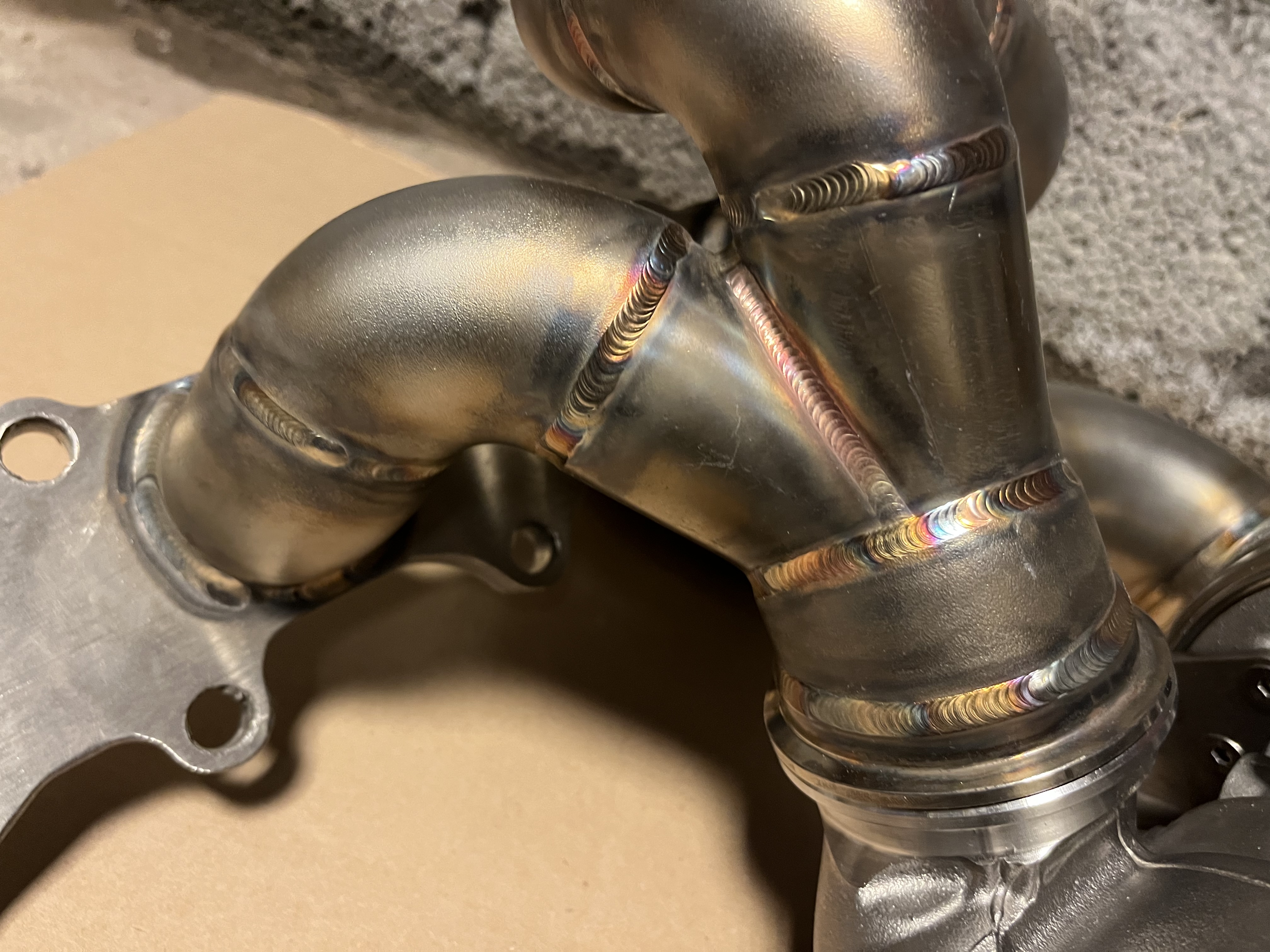
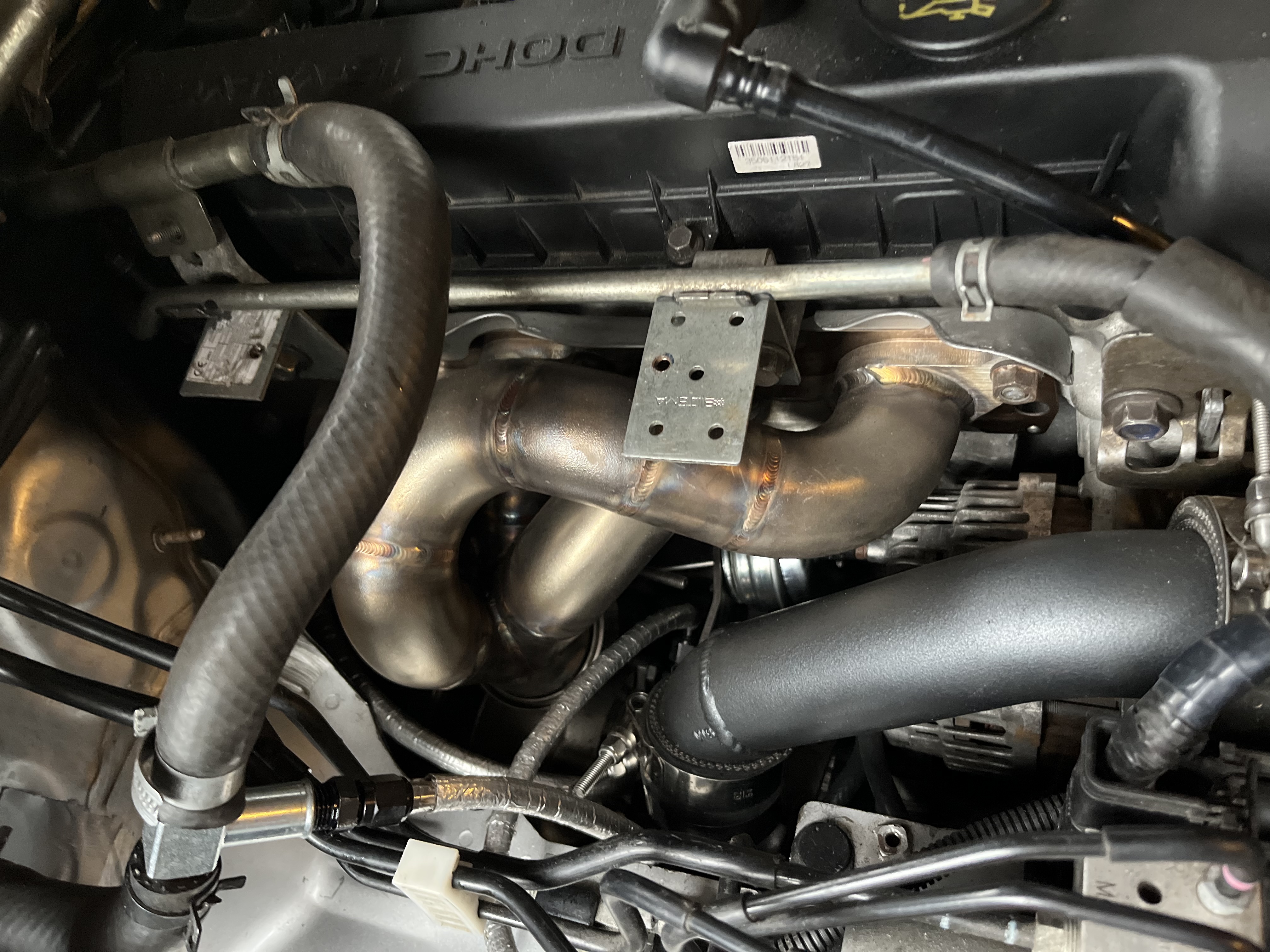
Manifold and down pipe is a work of shiny art. I just started TIG “welding” myself and have crazy respect for fabricators that can pull off something like this.
 |
 |
 |
 |
 |
 |
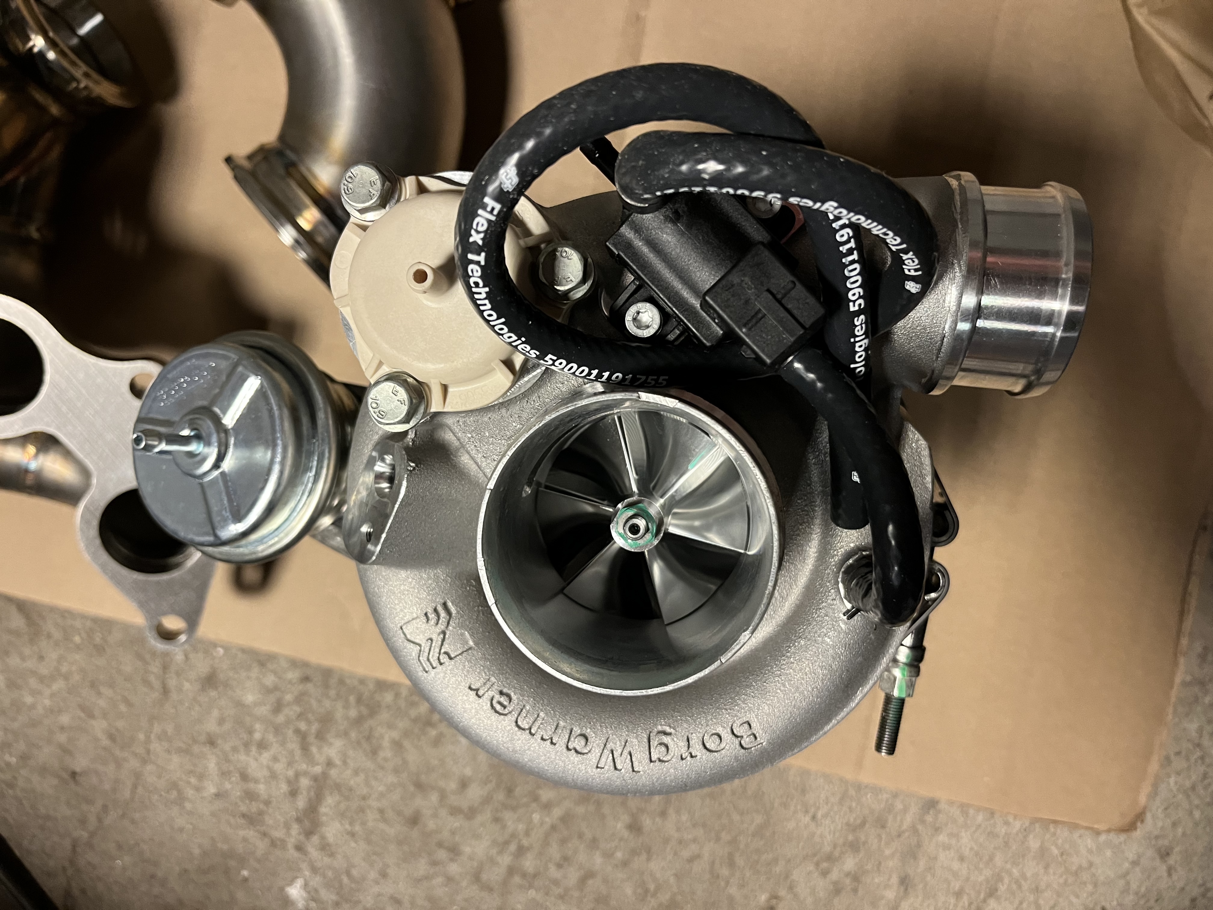
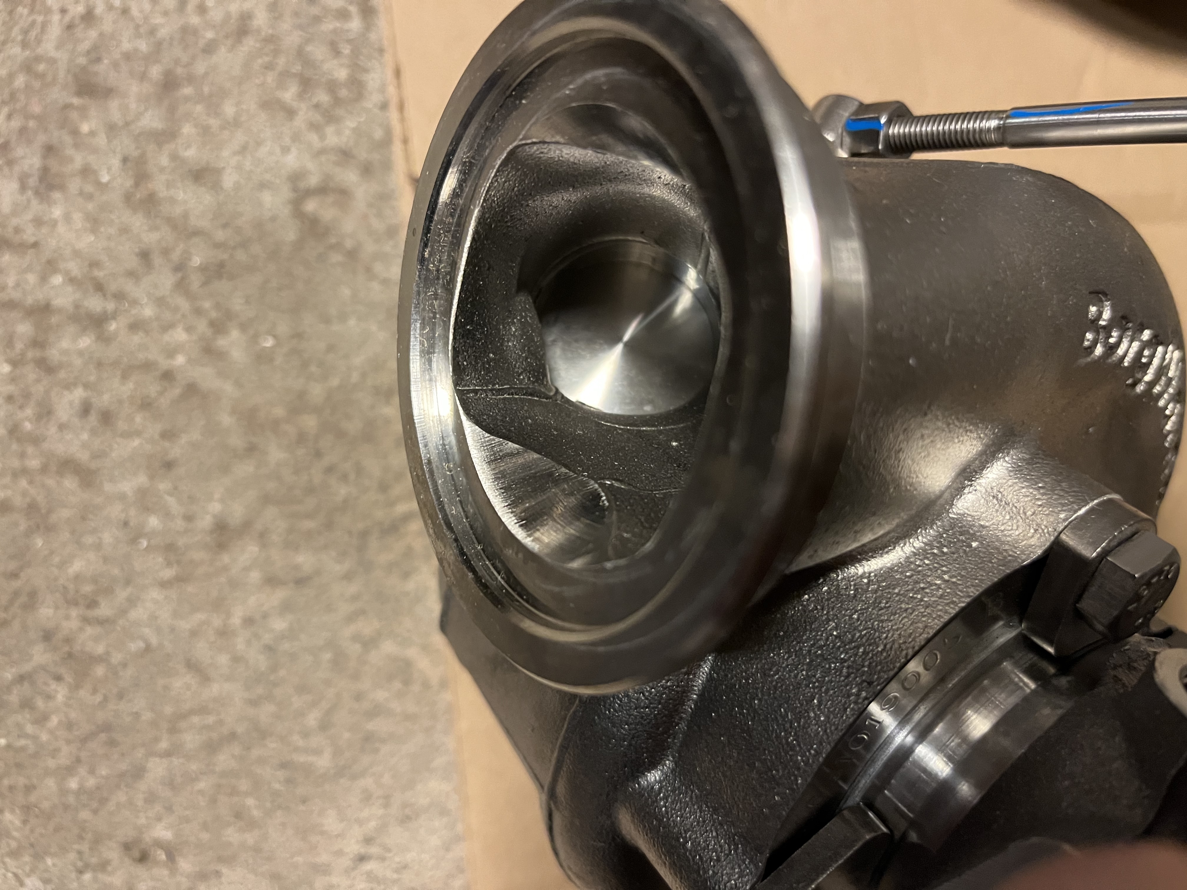
I ended up with an EFR7263 turbo which is at least one size bigger turbo than I had planned. I ordered a 6758 but that turned out to be discontinued and 6258 was originally sized for the 2.0. The goal for this conversion is for once not to make the most power, but a reliable 300 whp. The fragile L5 ring lands will appreciate the larger exhaust housing and lower back pressure, but it will cost some spool.
 |
 |
 |
 |
 |
 |
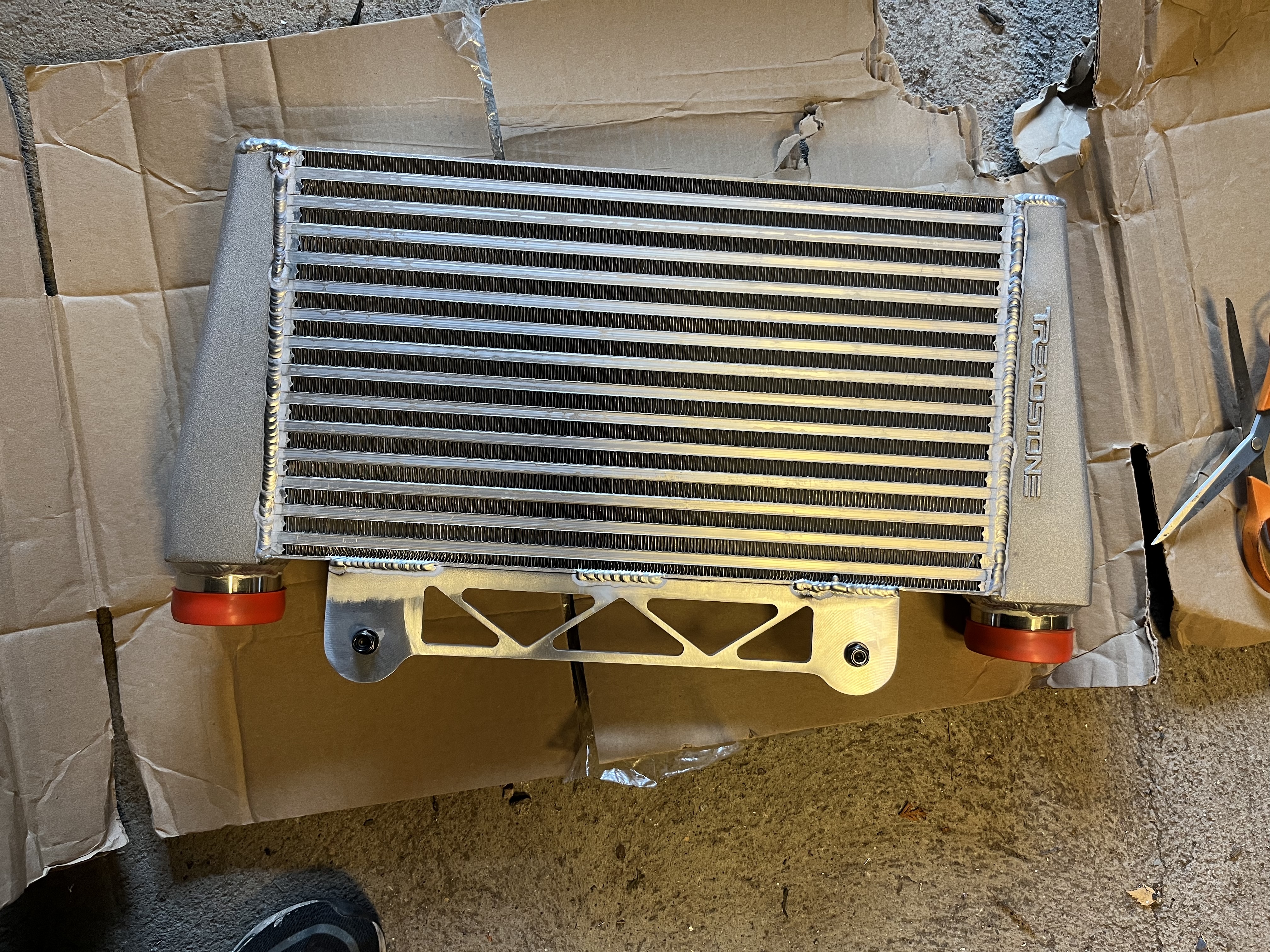
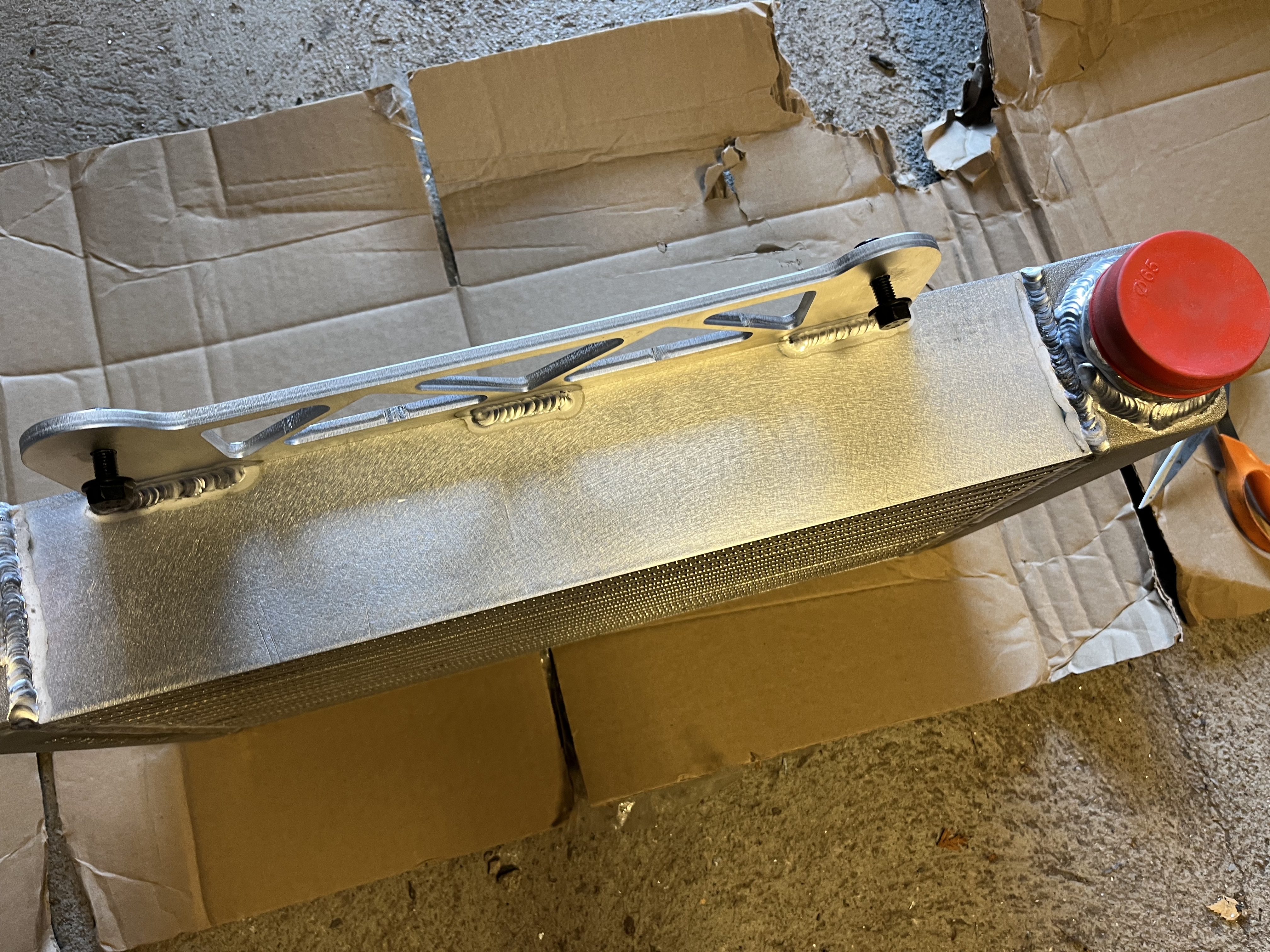
The inter cooler seems decent. Core has a thickness of 85mm.
 |
 |
 |
The rest of the parts, sans piping. The filter is way too small imho. Filter area is at best 1/3 of stock filter.
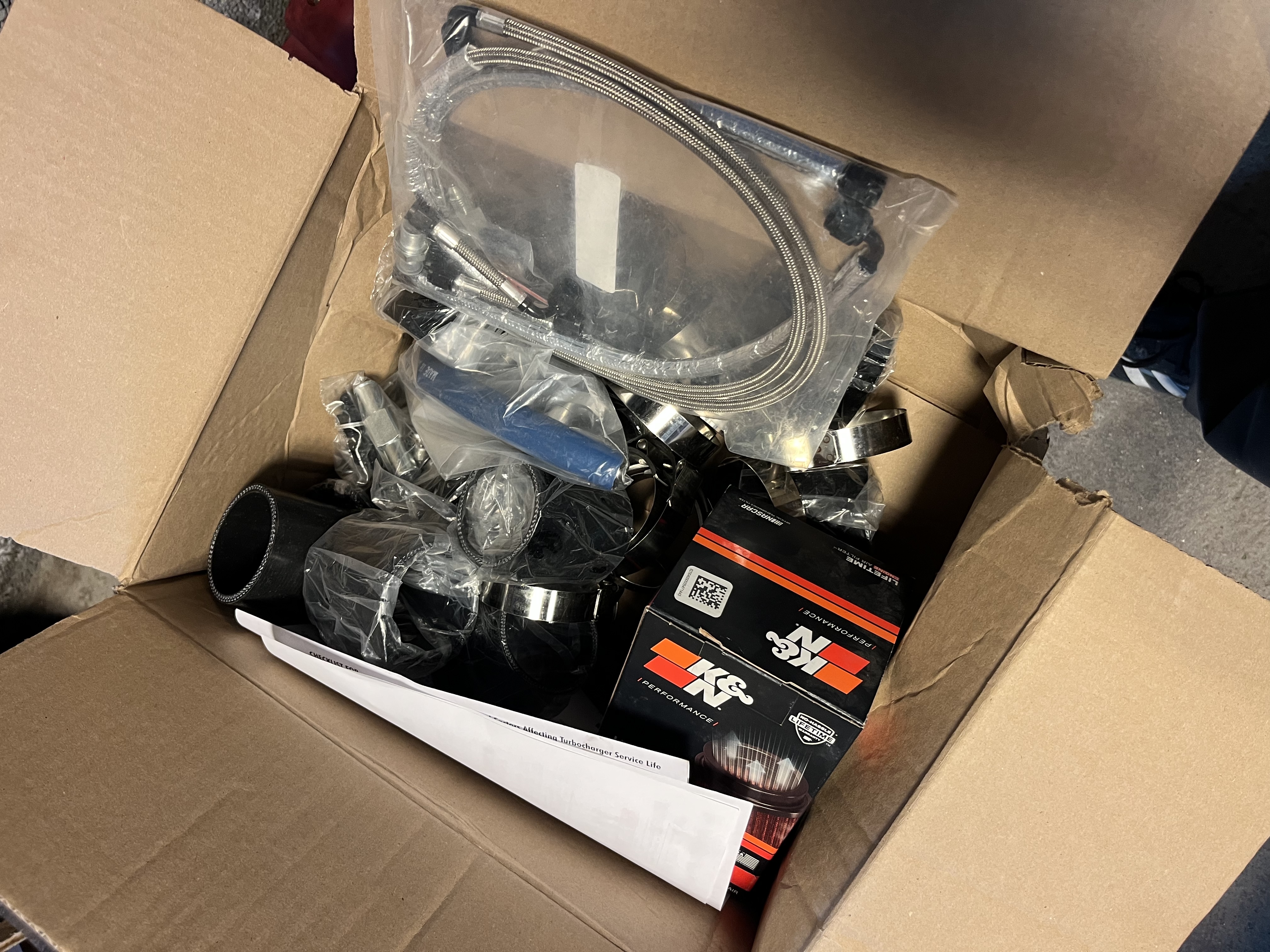
Weight of parts (Kg):
- IC 9.2
- piping 2.7
- Turbo 6.6
- Manifold,down pipe,v-band 5.8
- Div clamps,hose,AN etc. 3.6
Total: 28 Kg
Probably less than the FMSC/Cosworth supercharger.
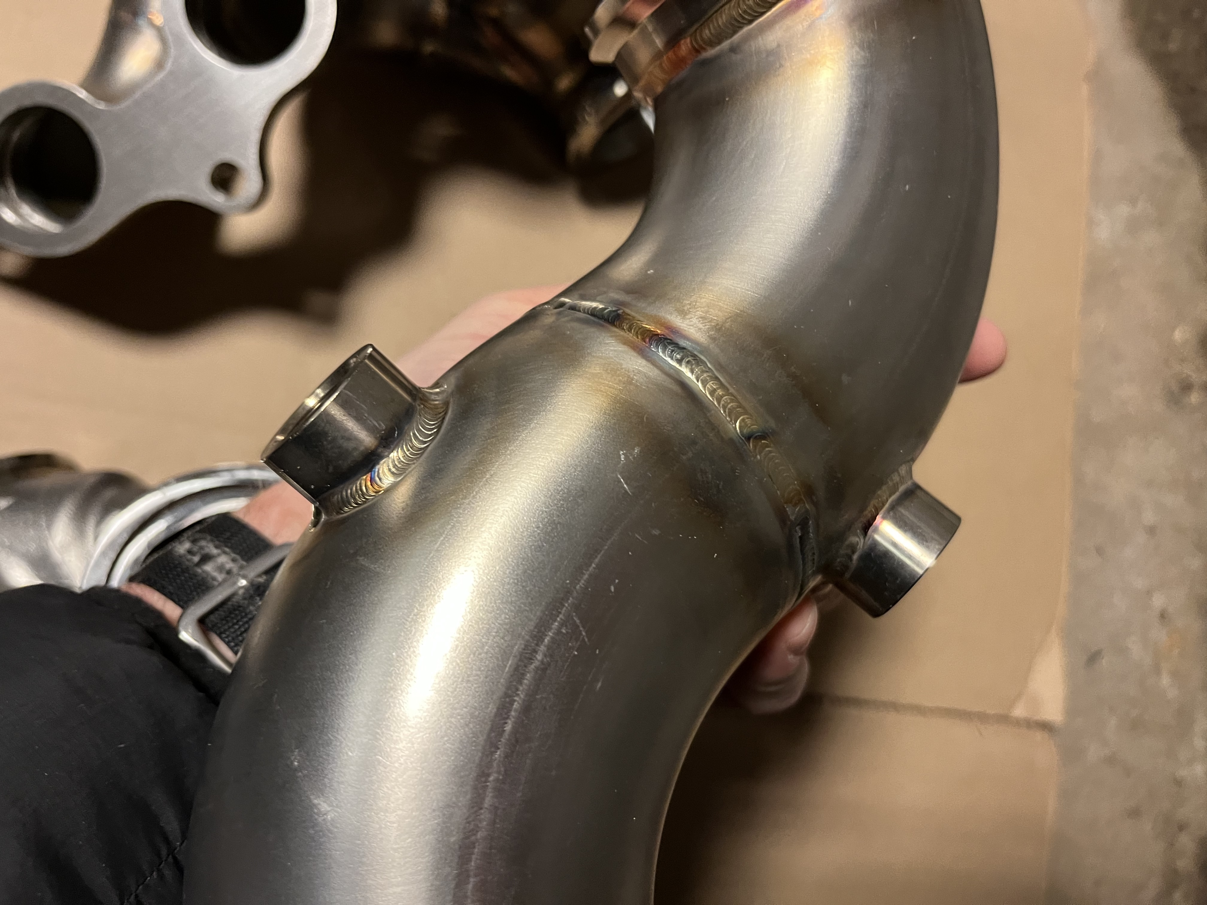
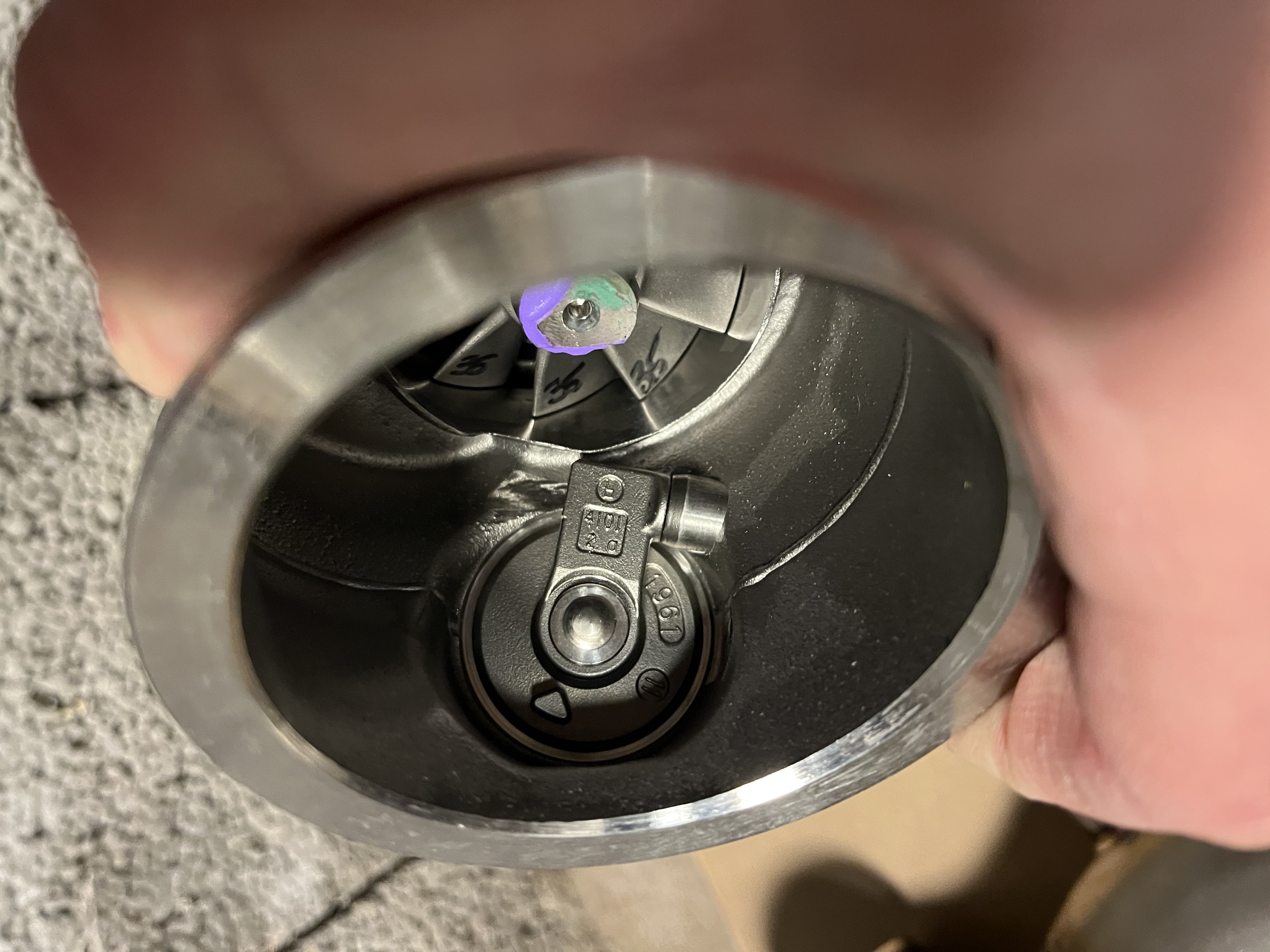
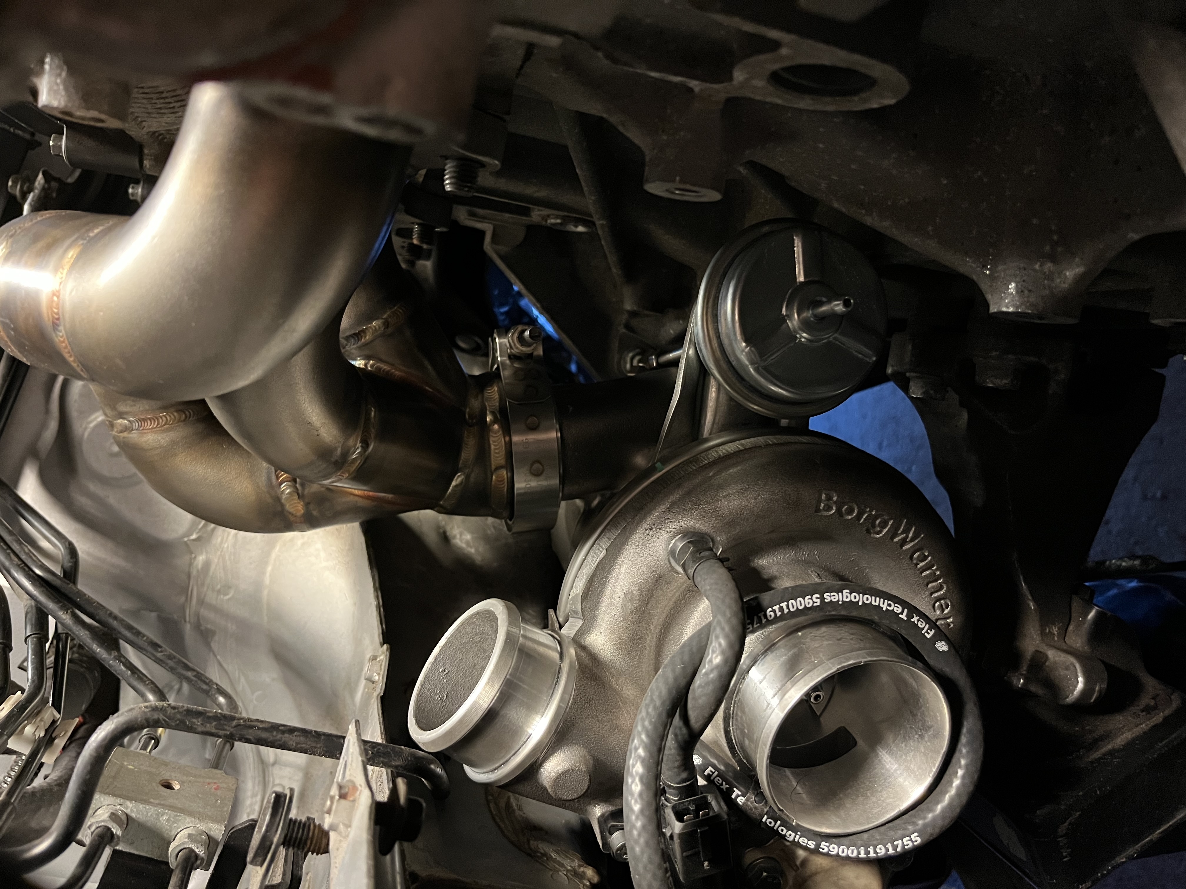
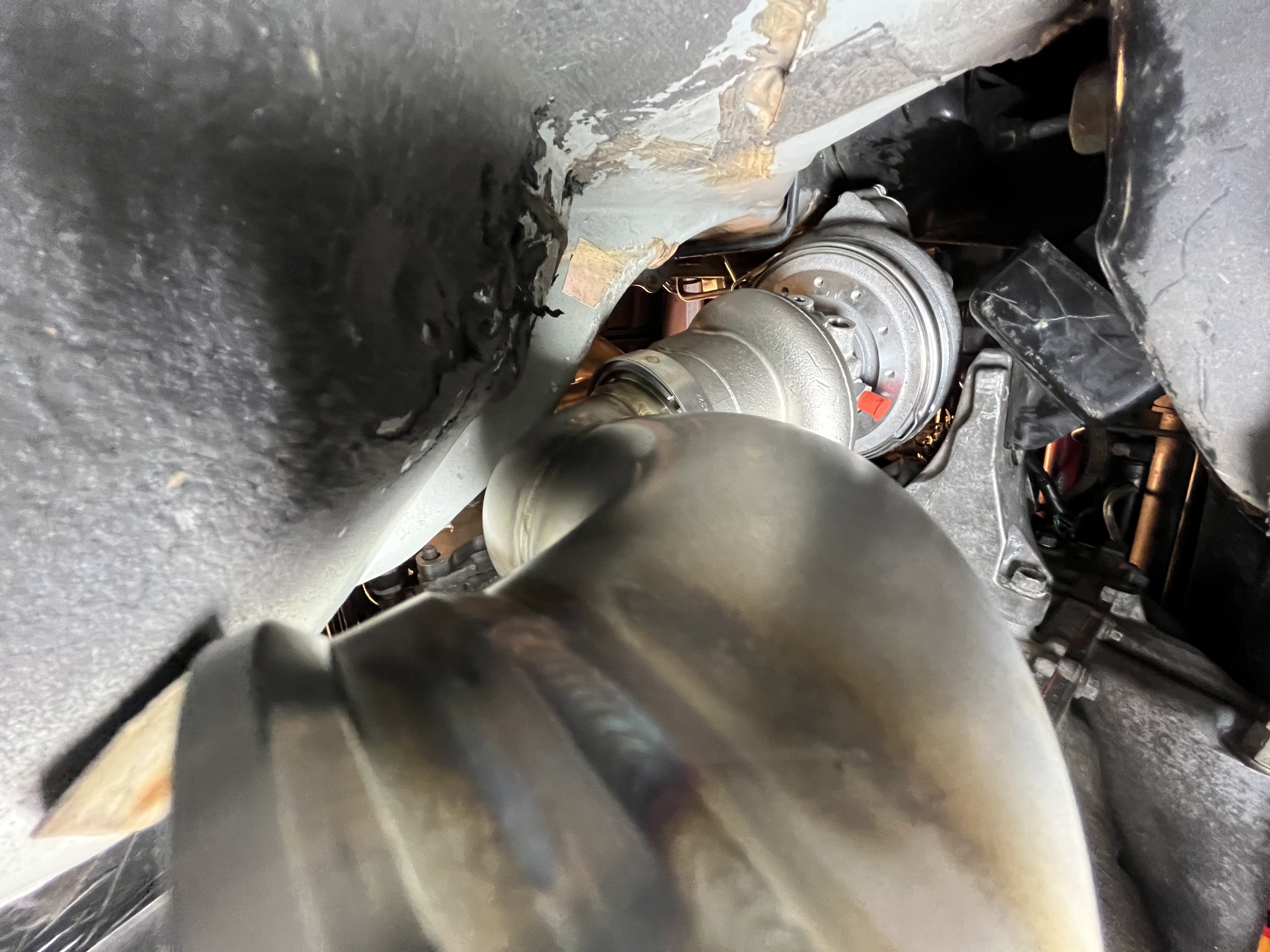
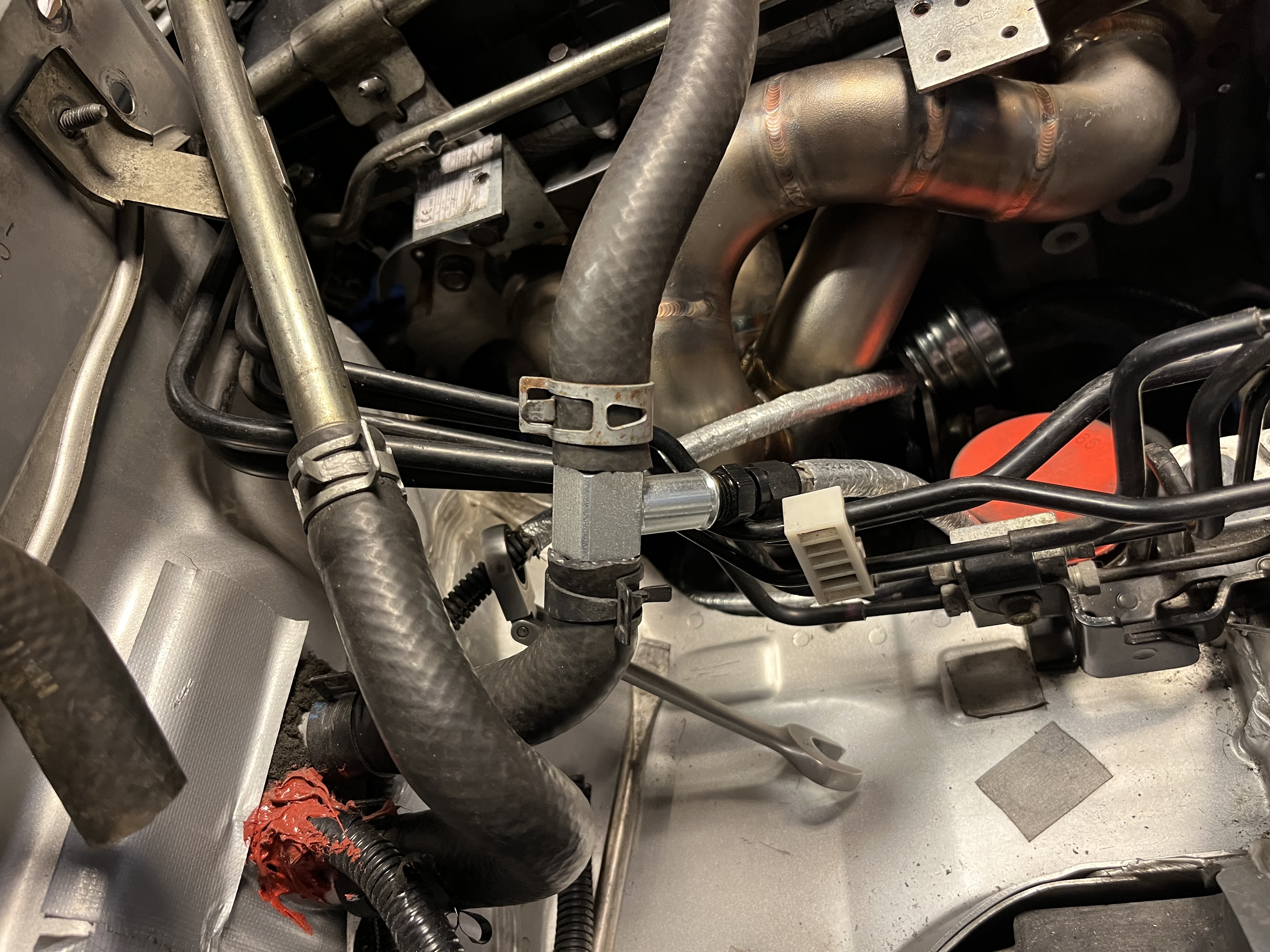
Test fitting hot parts. V-bands make the alignment easy, although getting the turbo/manifold combo in was tricky as it can not be installed assembled. I ended up elongating the holes to move the ABS outwards to get better clearance. The IWG is the reason this is a bit tight. I later re-clocked center section and IWG mounting on the compressor housing to gain more space towards the engine block.
 |
 |
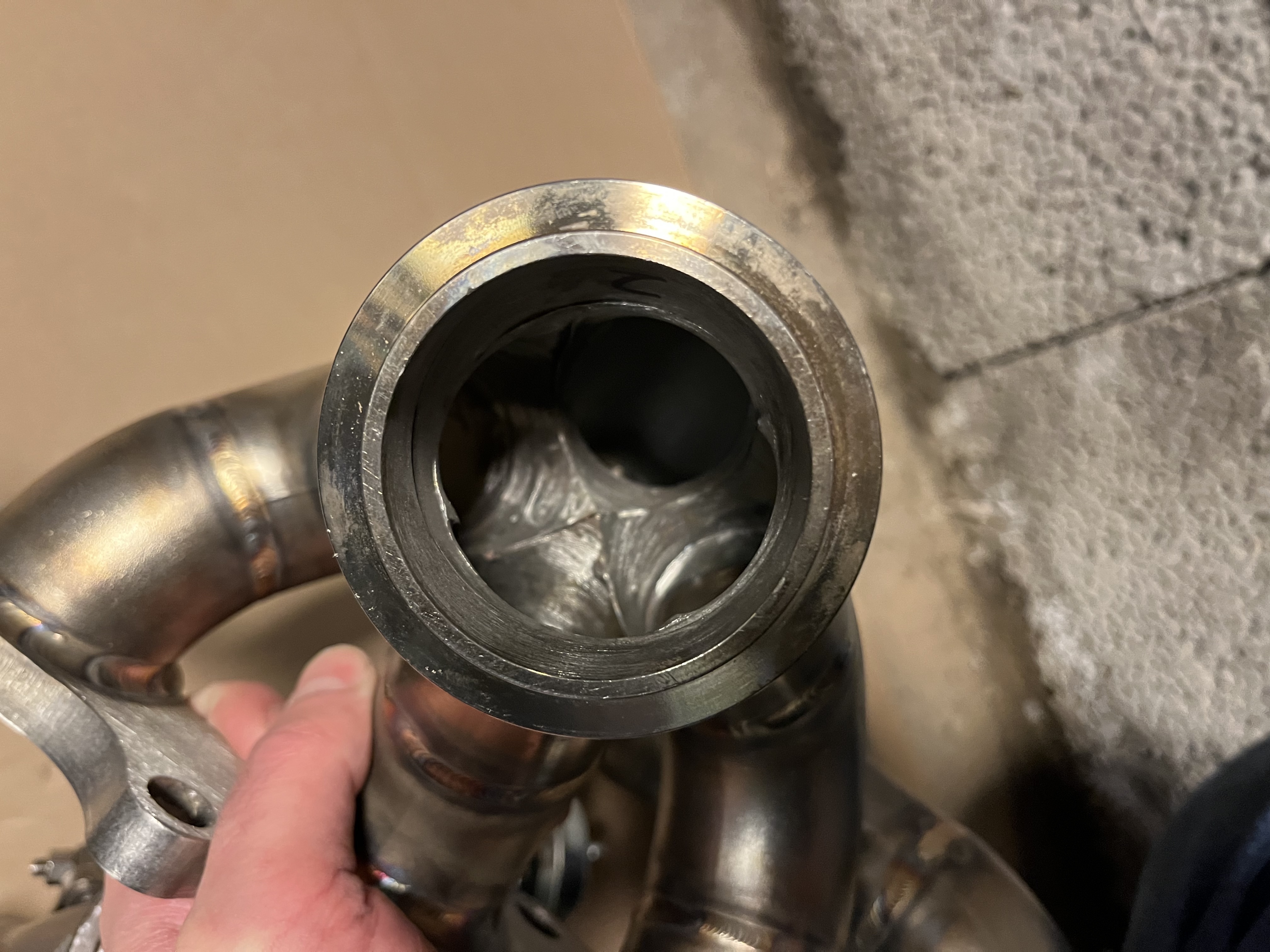
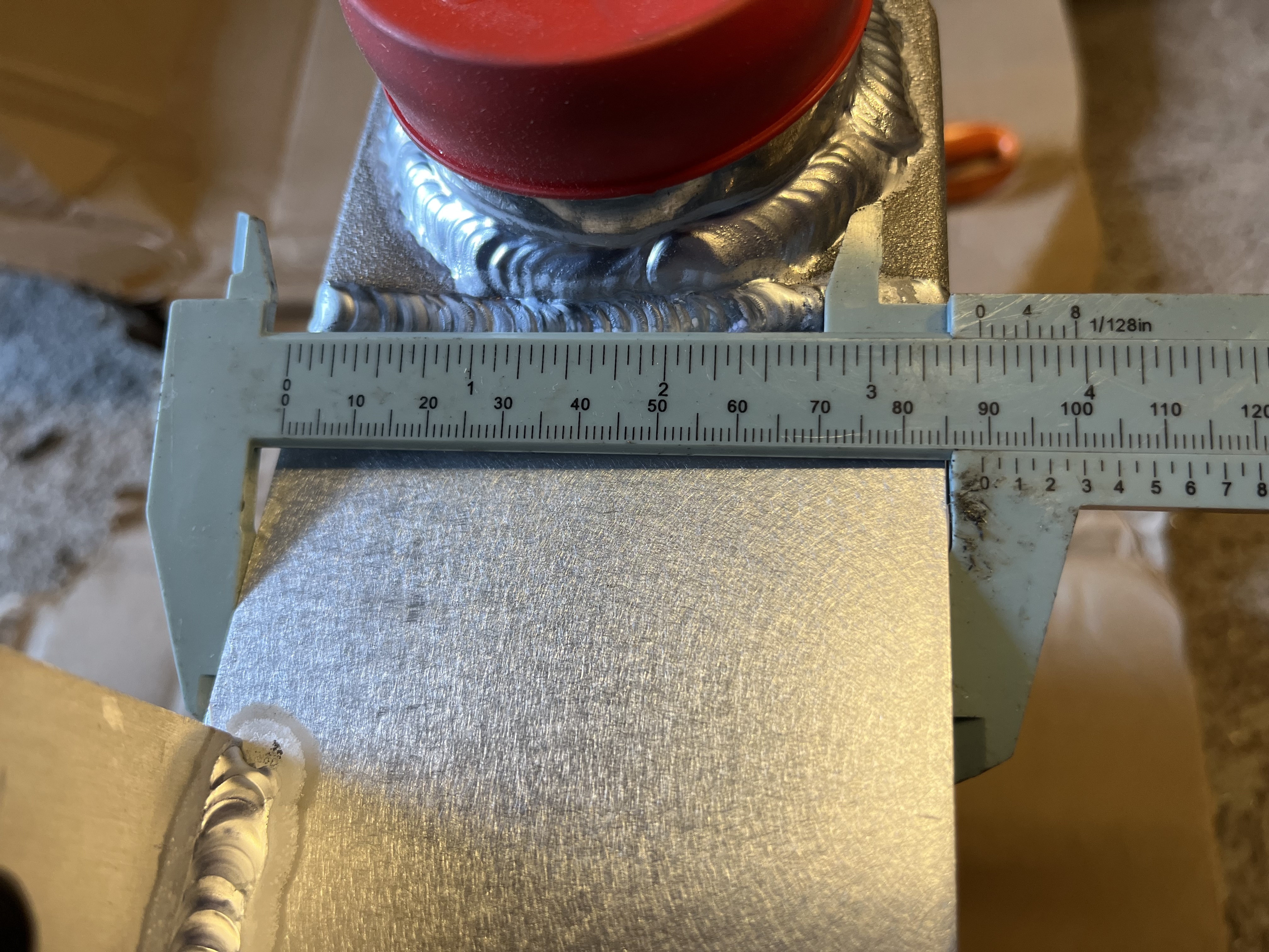
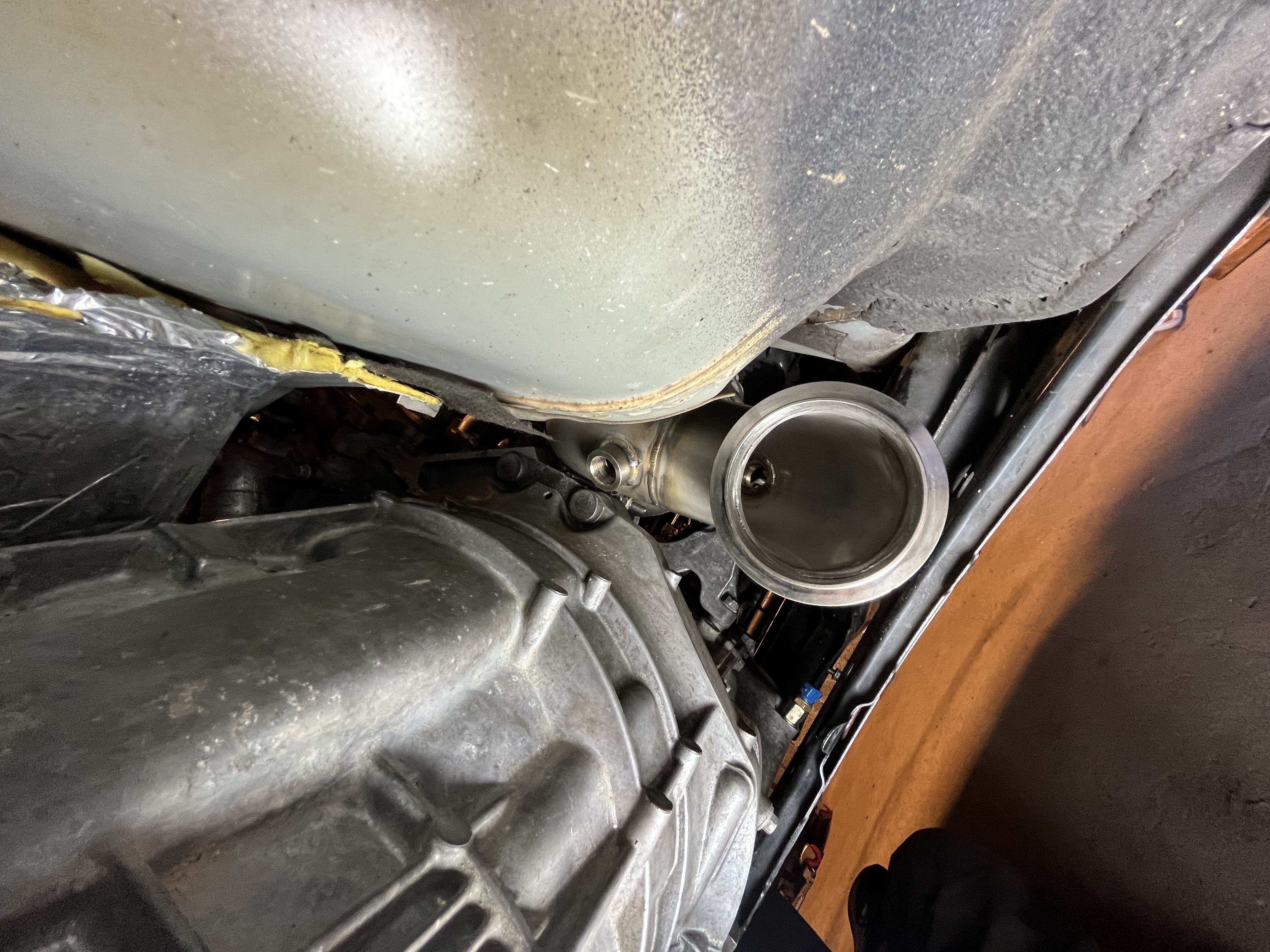
Down pipe is 3” and has a nice fit with good adjustability from the v-band. I later added some corrugated aluminium heat shielding to the tunnel. Might add more around the brake lines and on the side of the block.
 |
 |
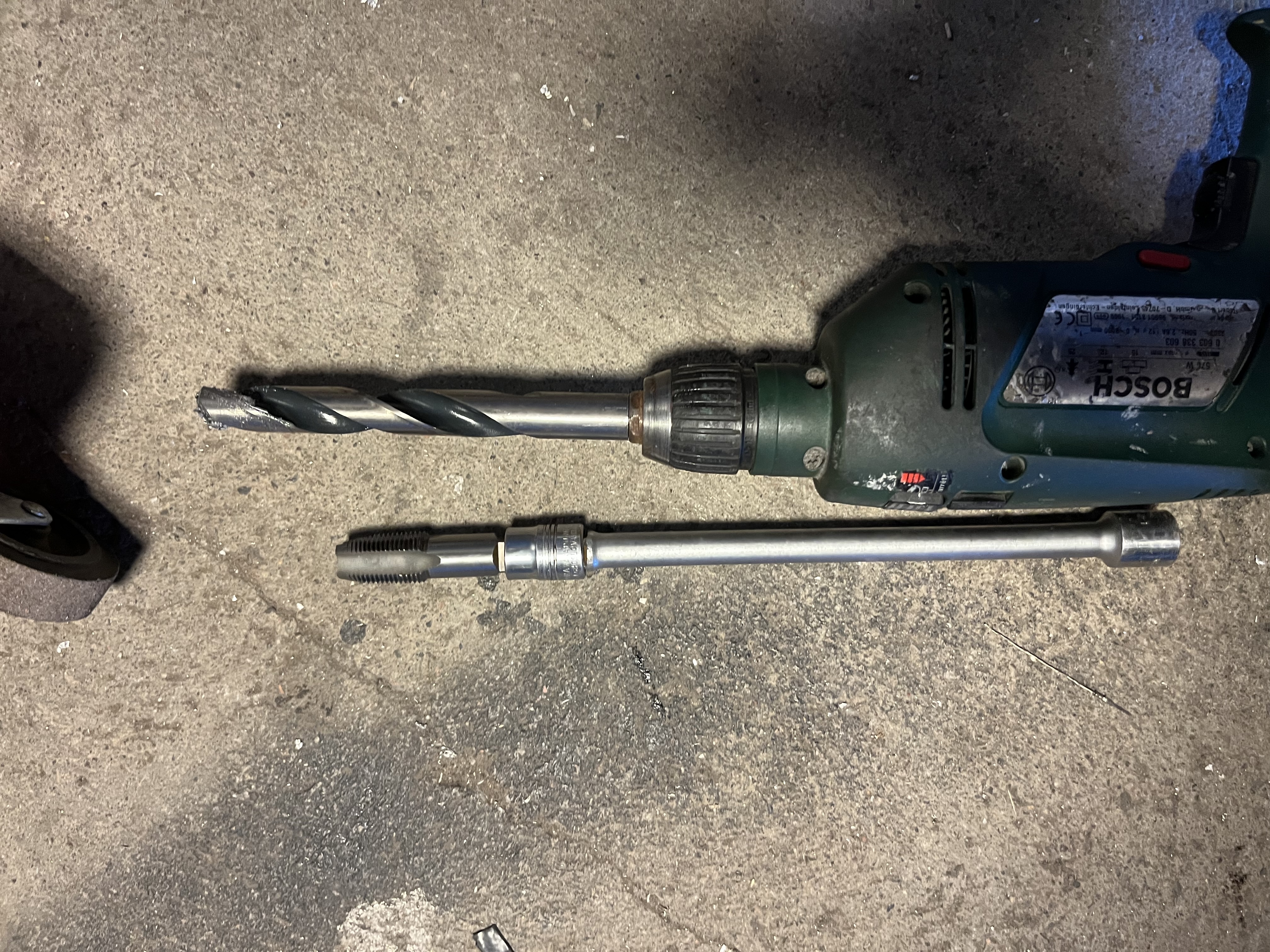
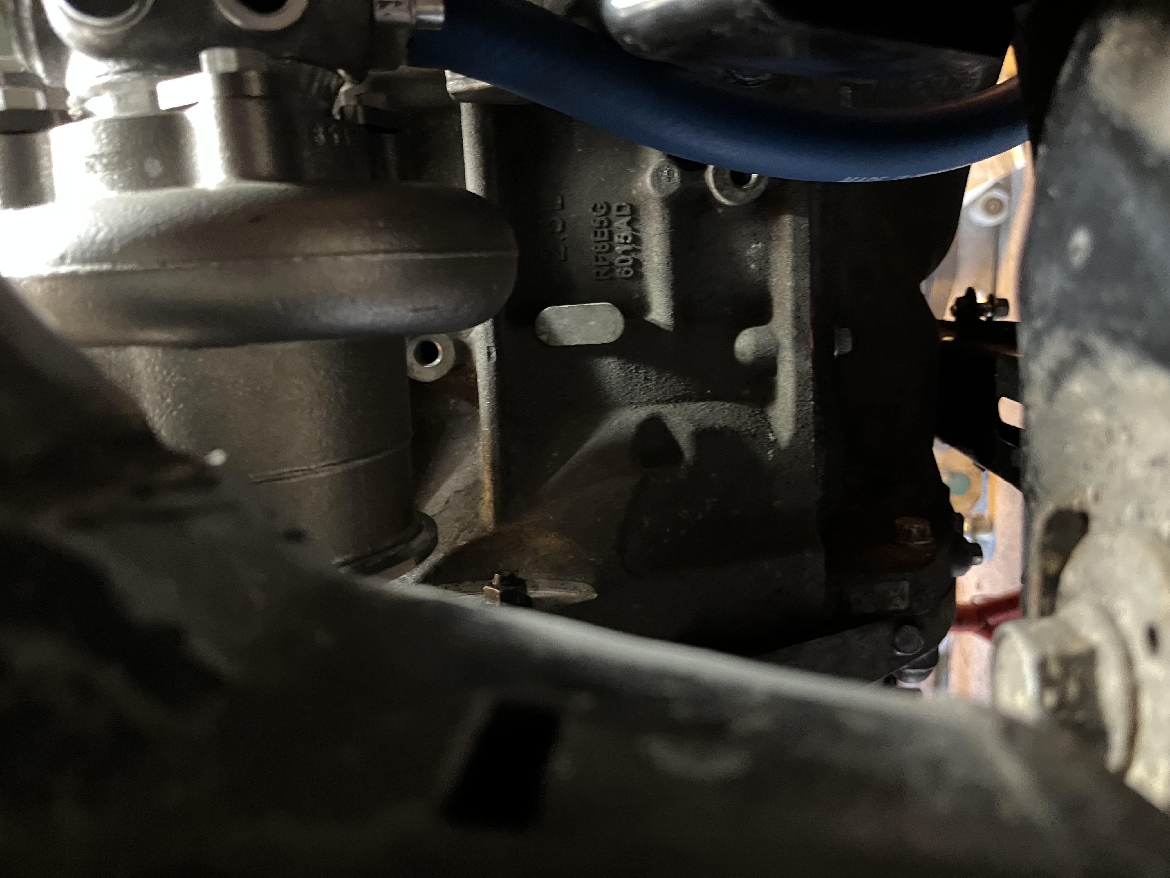
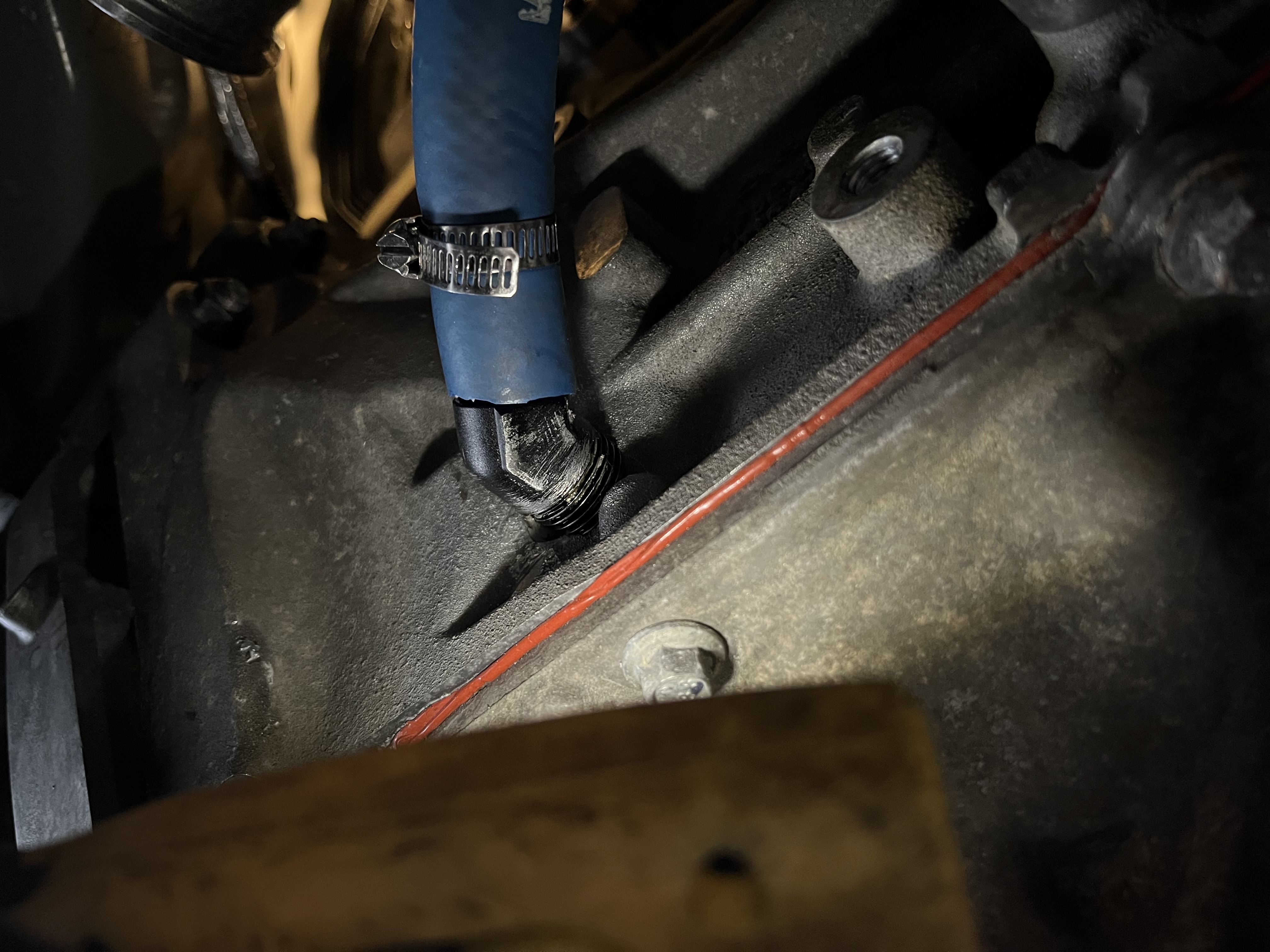
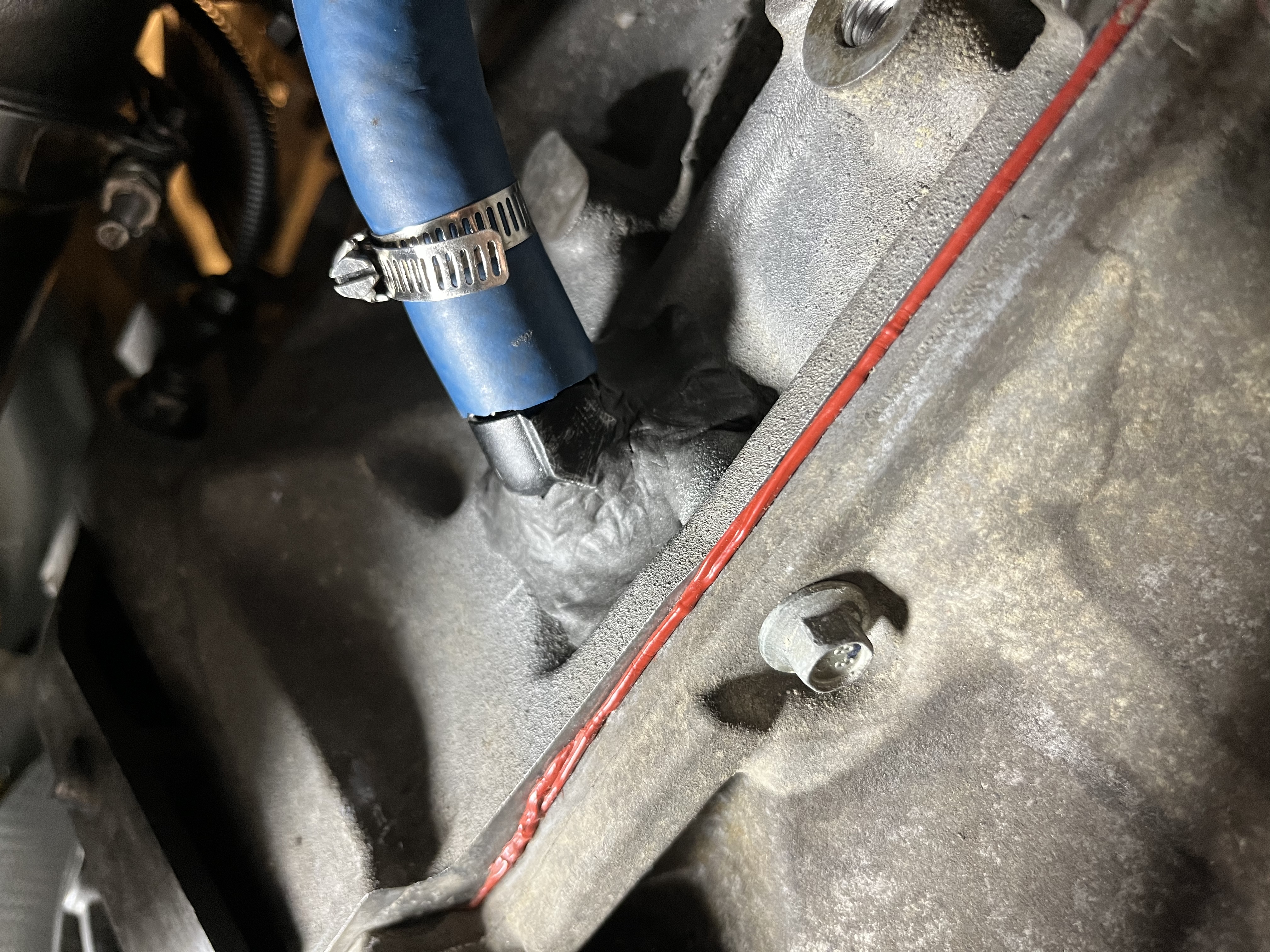
Then the hard part of the install, drilling the block for the turbo oil return.
For some reason I got the GT Turbo install doc and not any specifics for the EFR install with the kit (mail).
I first thought it was a submerged install in the oil drain plug as described in the GT manual but was missing the parts.
Turns out there was a second PDF for the EFR specifics.
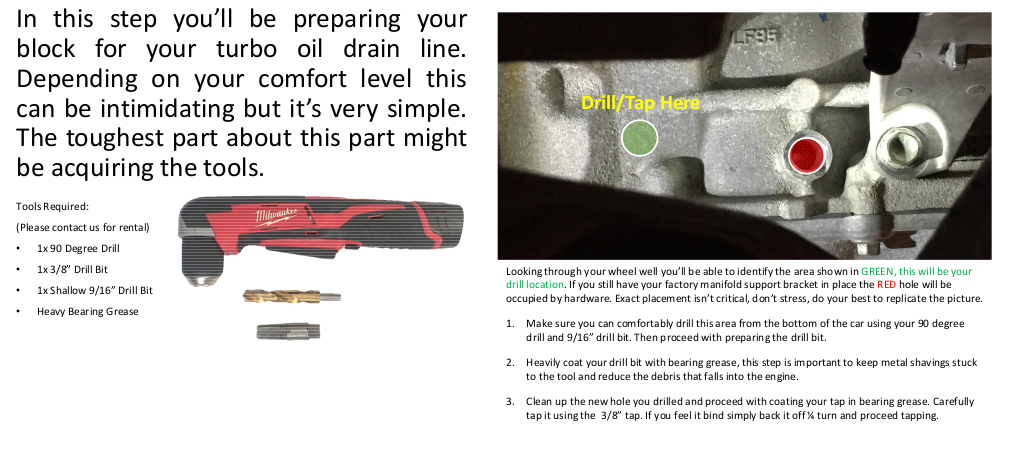
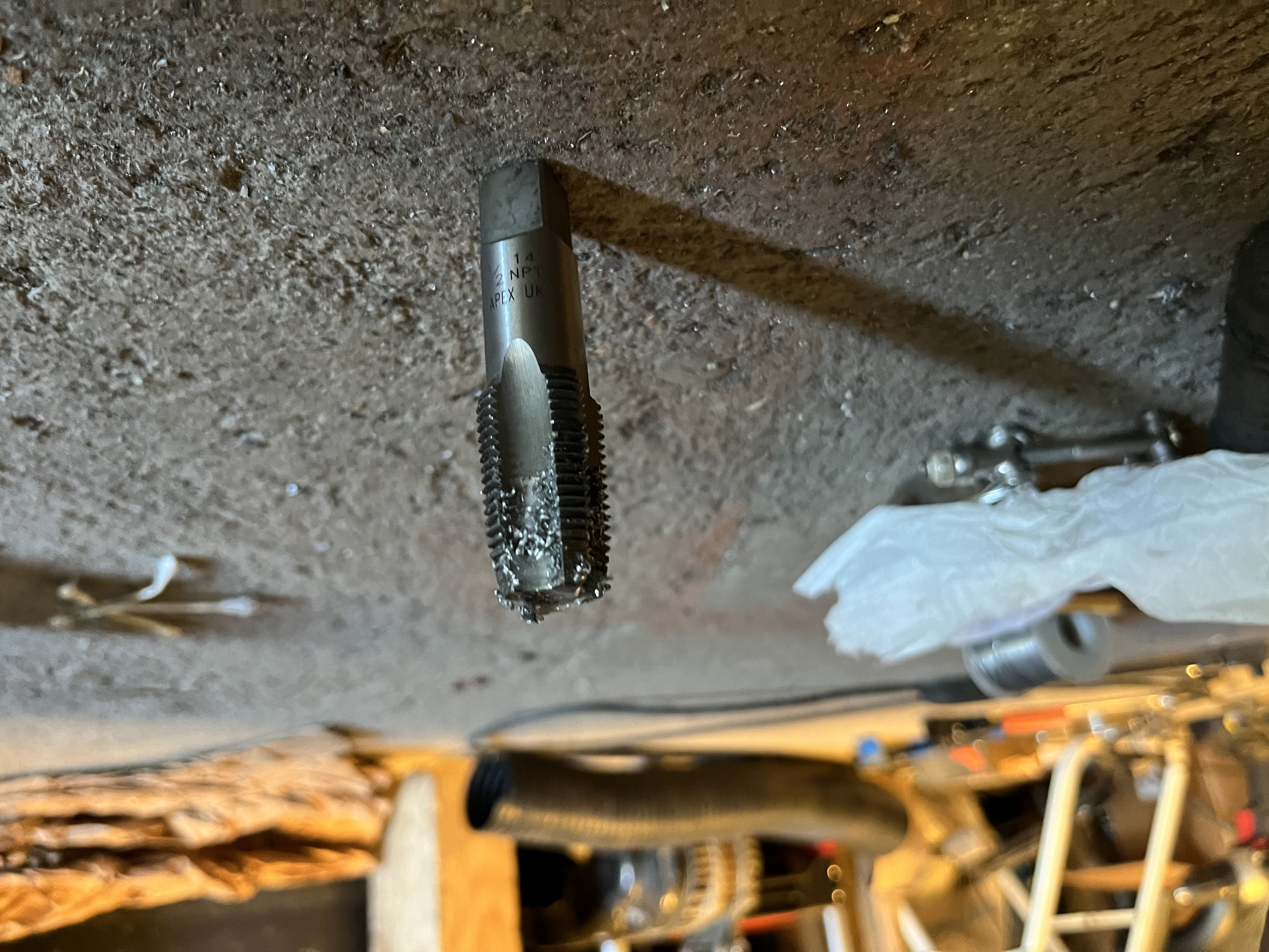
The info on the drill/tap did not match the 1/2” Vibrant oil return flange so luckily I measured it before I spent $100 on tooling.
 |
 |
The actual drilling was hell. Disclaimer, I did not use a 90 degree drill… but there is room for standard drill in trough the wheel well. It’s not visible in the instructions, but particular location for the hole is actually angled, so a pilot hole is very much recommended.
 |
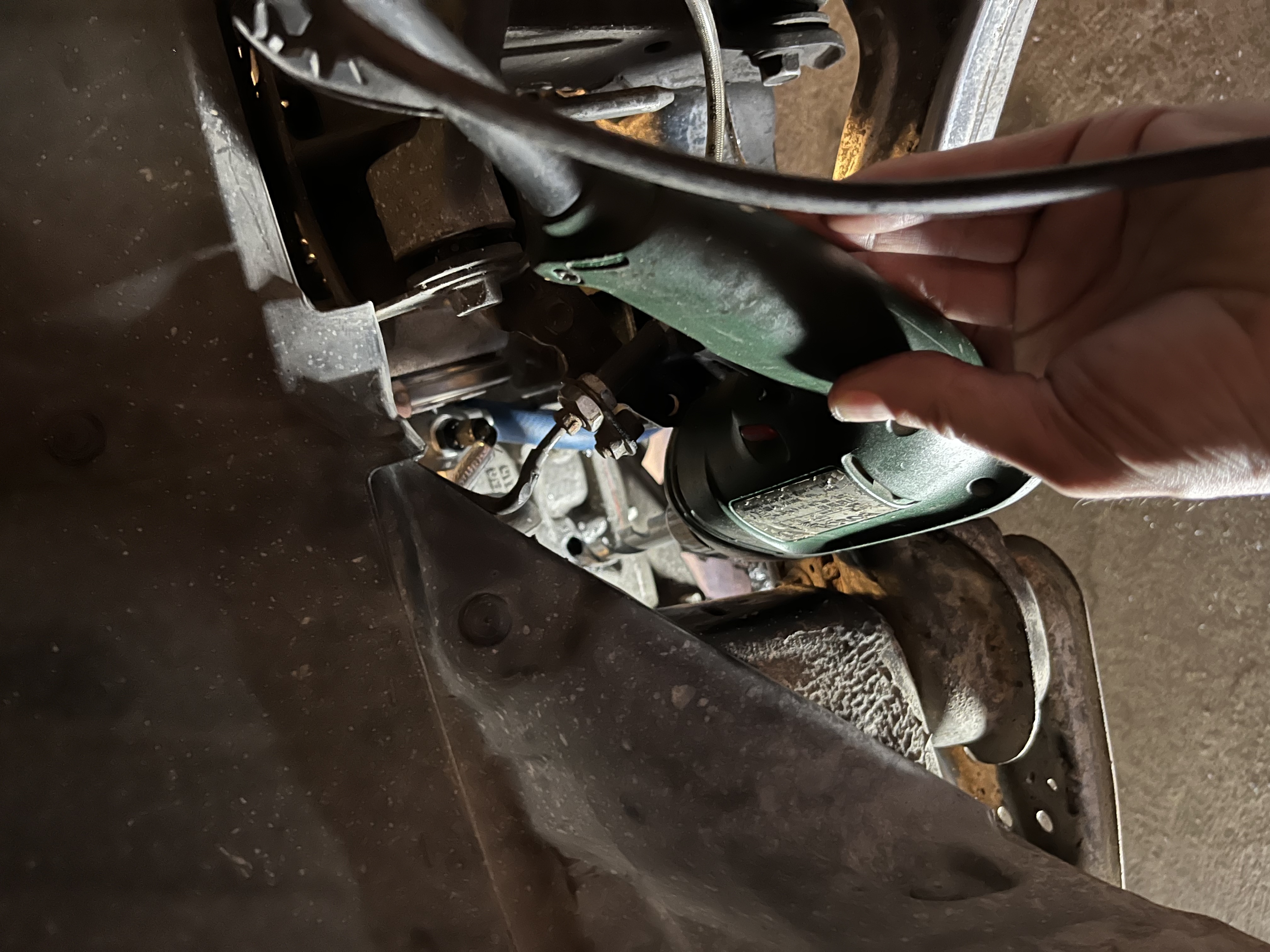 |
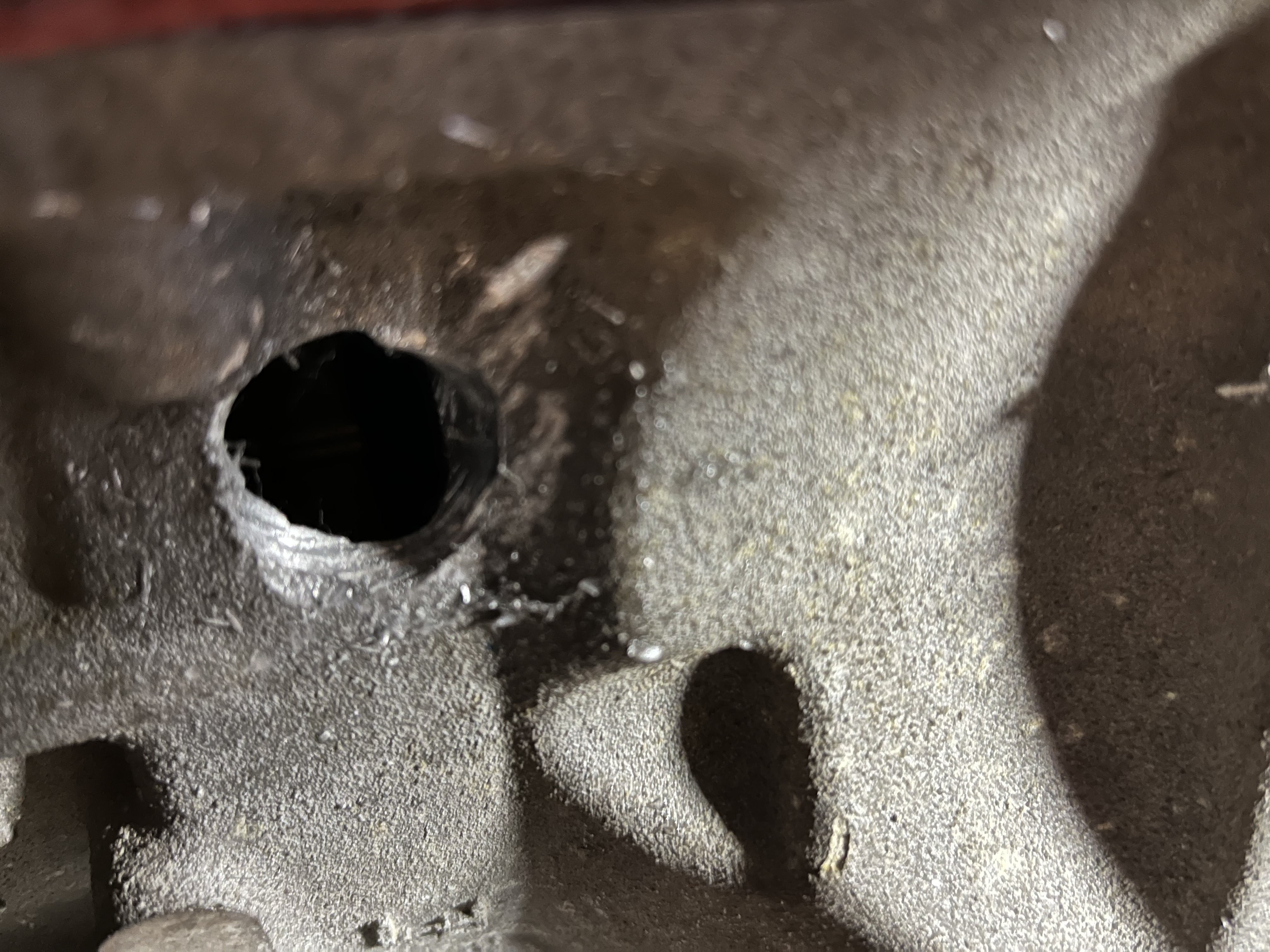
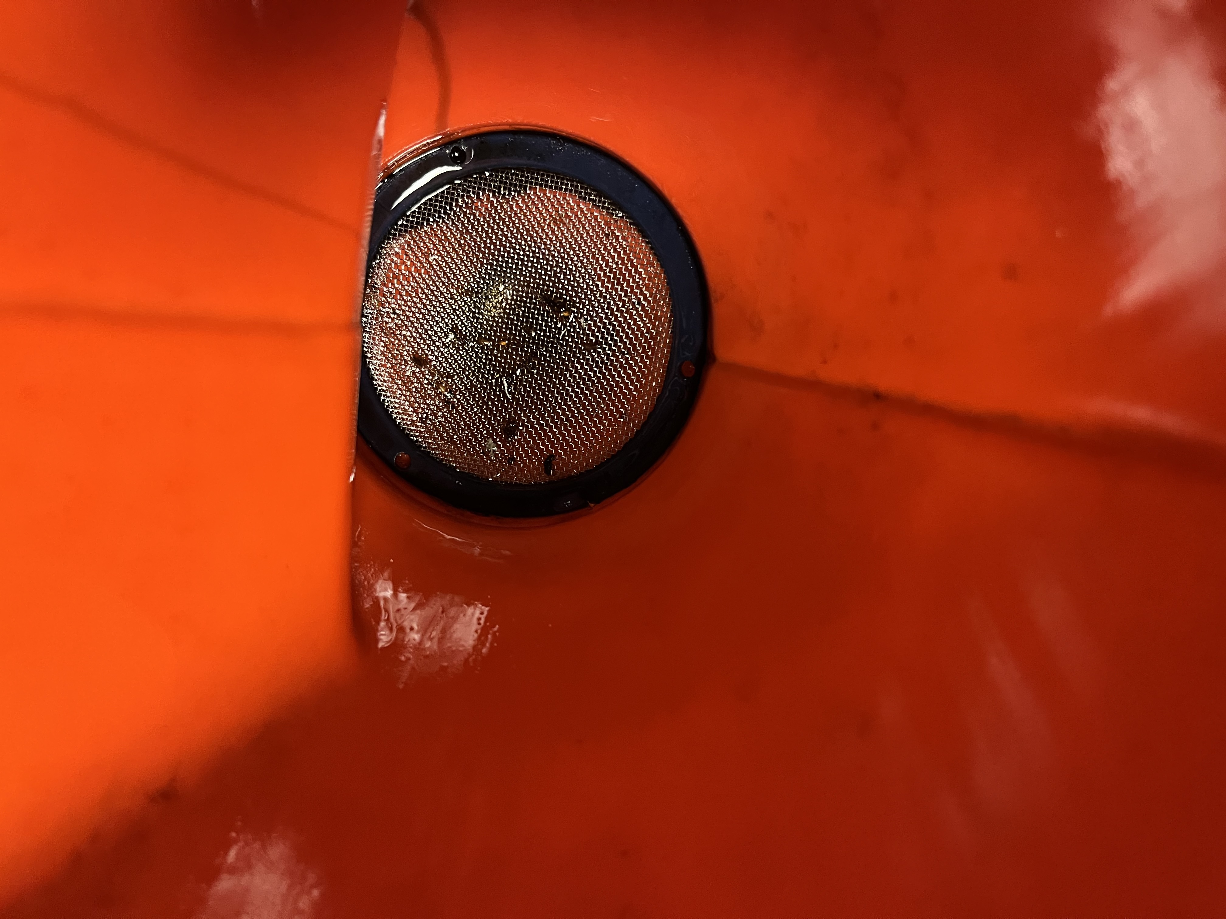
The thickness of the block is no more than 5-6mm which means there are limited threads cut when tapping. Since it’s at an angle as well the threads are engaging uneven across the flange. It might work tapping it flat angeling down but that would result in some pooling of oil. I tapped the hole by using an extension which worked very well as I could align it securely with no directional movement.. It’s almost impossible to catch all the metal with grease. Spent some time fishing out metal/grease mix from the inside of the threaded hole with angled cotton swab. Finished off with flushing 2l of white spirits trough the flange which resulted in some metal flakes in the screen of the funnel.
 |
 |
 |
 |
I tried both thread sealant and tape on the flange but both resulted in oil leaking during initial testing.
I ended up degreasing thoroughly and adding LOTS of JB Weld which seems to hold.
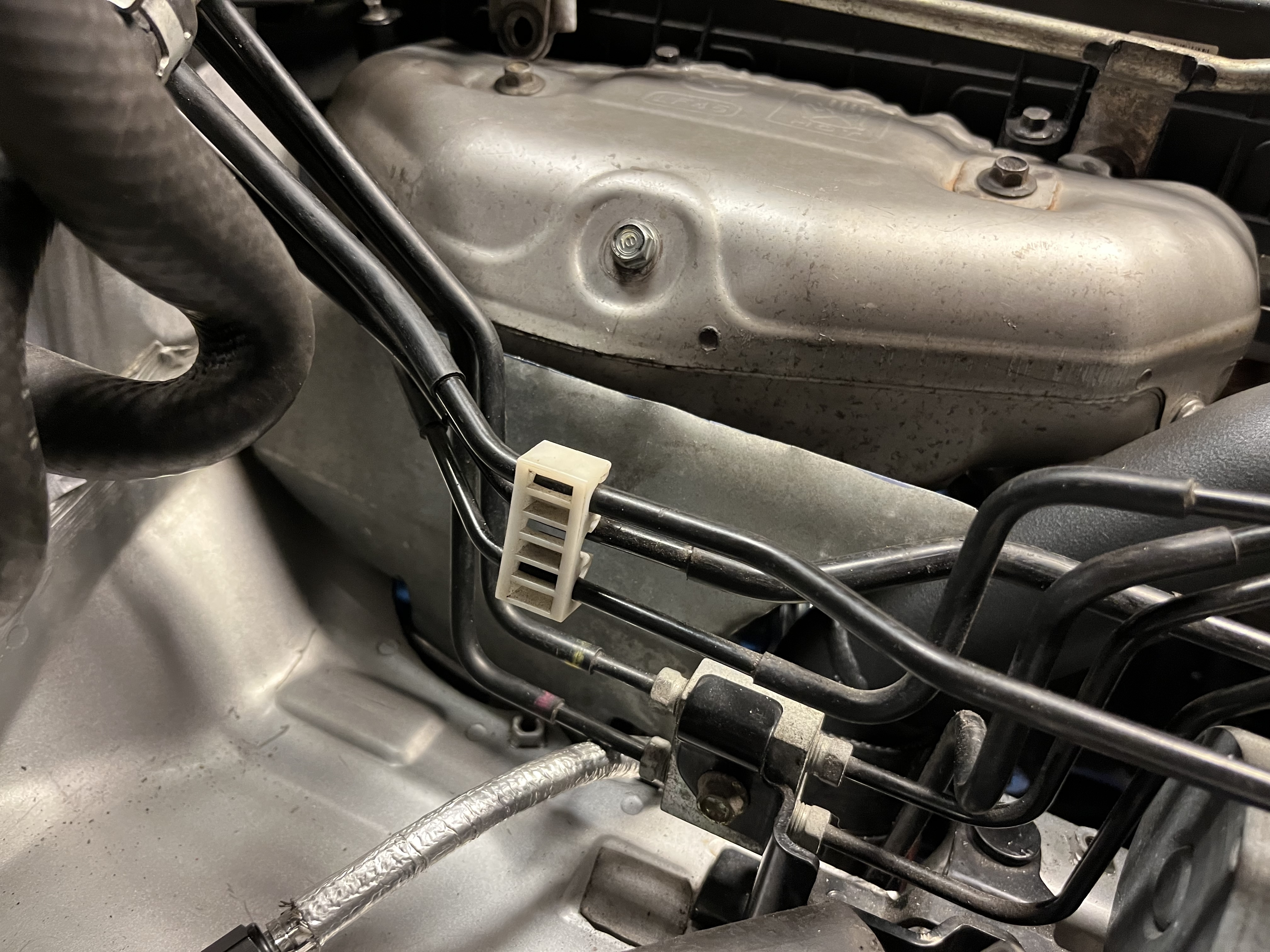
Both oil feed and turbo coolant are braidend and heat insulated AN lines. I wish the coolant feed line was a bit longer and had more low profile T-piece. The turbo coolant return is plumbed into the hose from the expansion tank and not visible. Some extra splicing was needed as I relocated the expansion tank to the waser fluid area instead of moving it to the middle. This was to to keep the the airflow out the bonnet vent open + keep the stock airbox …
 |
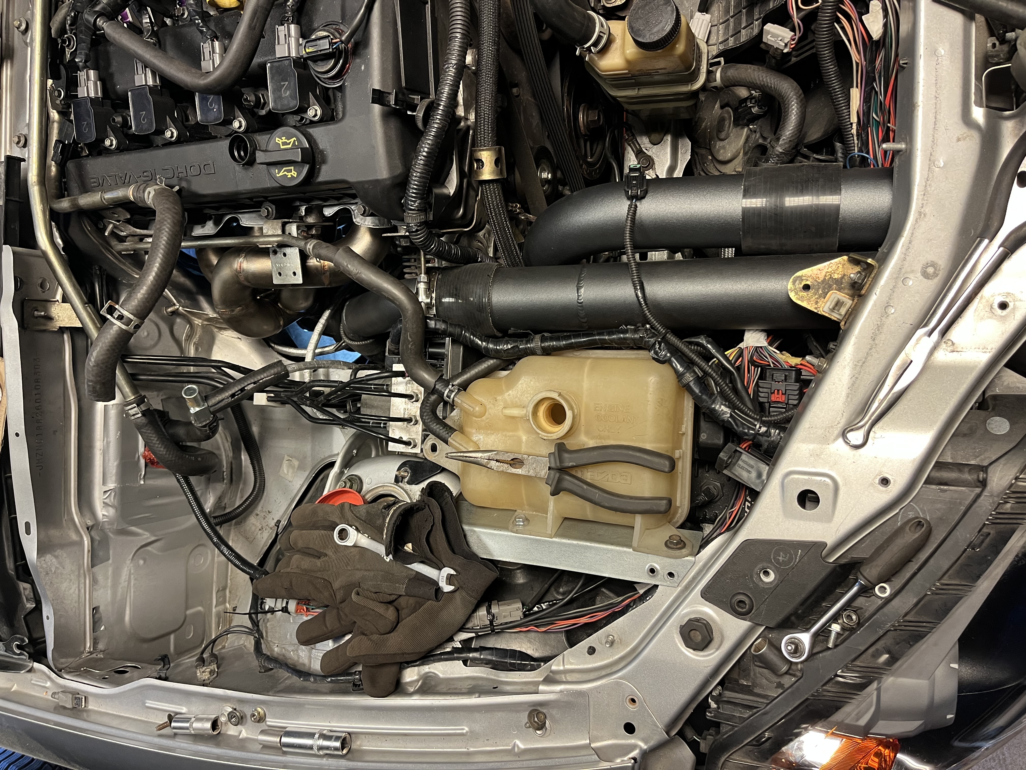 |
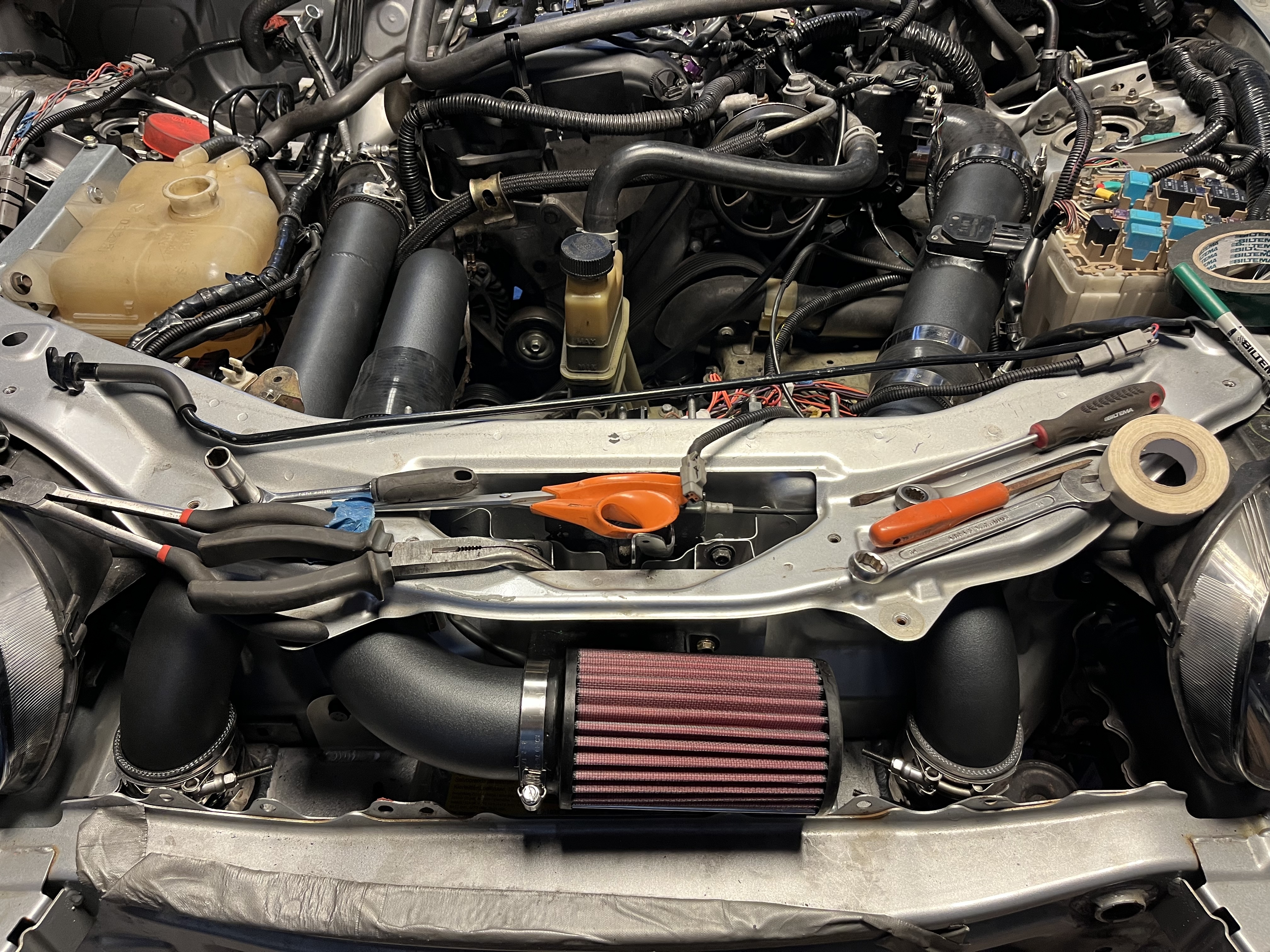
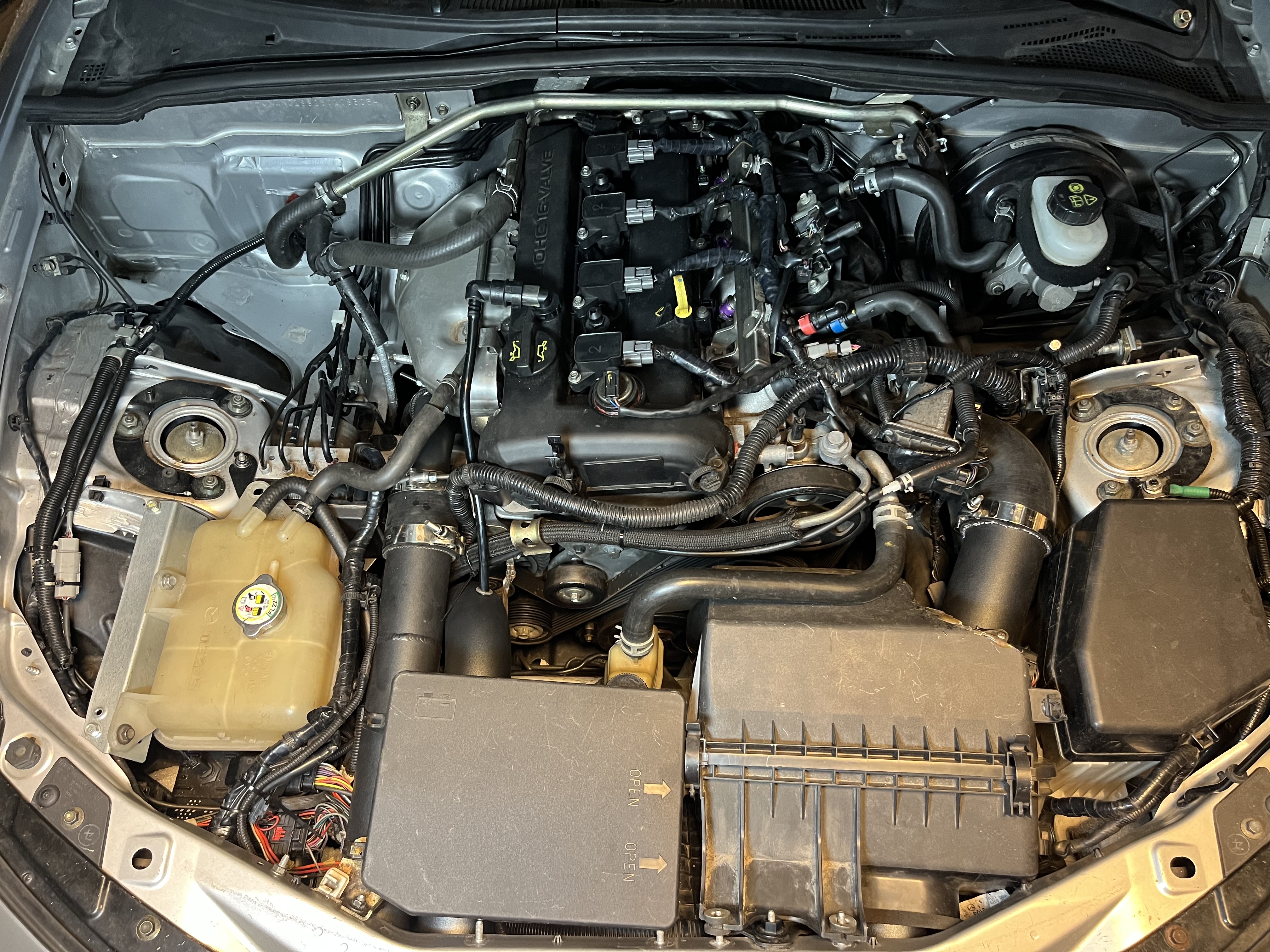
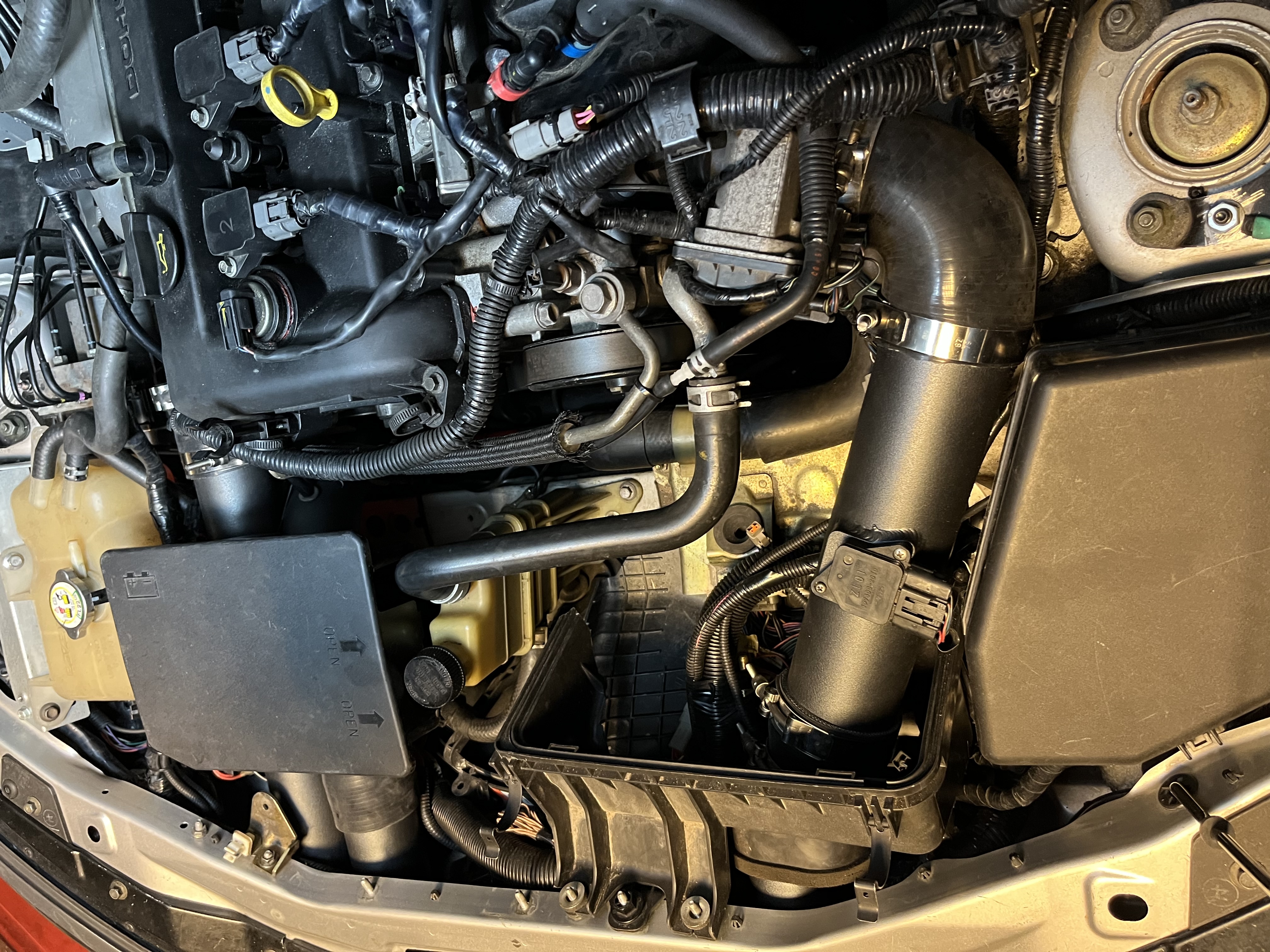
IC and intake piping was straight forward. Lots of clamps. I only use the MAF (modified) sensor for IAT. The filter is way too small IMHO compared to the stock filtered area. I do like the location for clean cooled air but will test a filter location in fog light area or directly on the turbo if IAT is not affected too much.
 |
 |
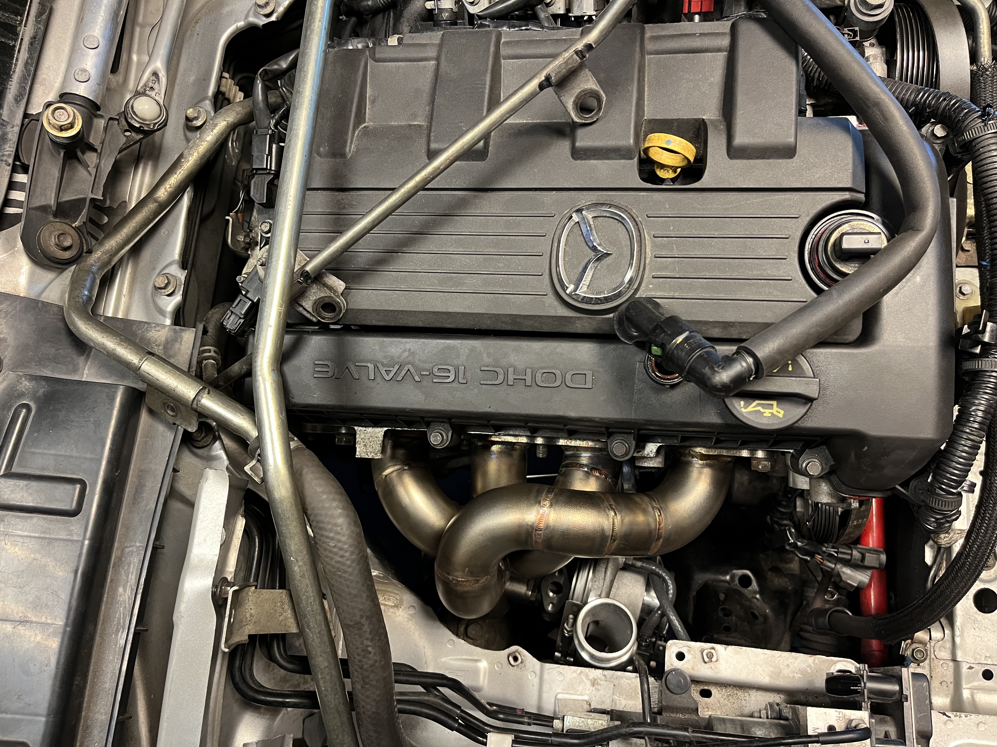
The stock manifold heat shield actually fits with minor modifications. This also includes the lower part which wraps nicely around the runners. Used some drilled angle brackets for mounting. Had to route the coolant bleed line a bit higher. Looks OEM except for the compressor exit.
 |
 |
To add some more stealth I modified a spare air box as a cover for the EMS wiring and pressure pipe on the intake side + just mocked up the battery cover as a test. I will revisit this later when I know what to do witht he intake.
 |
 |
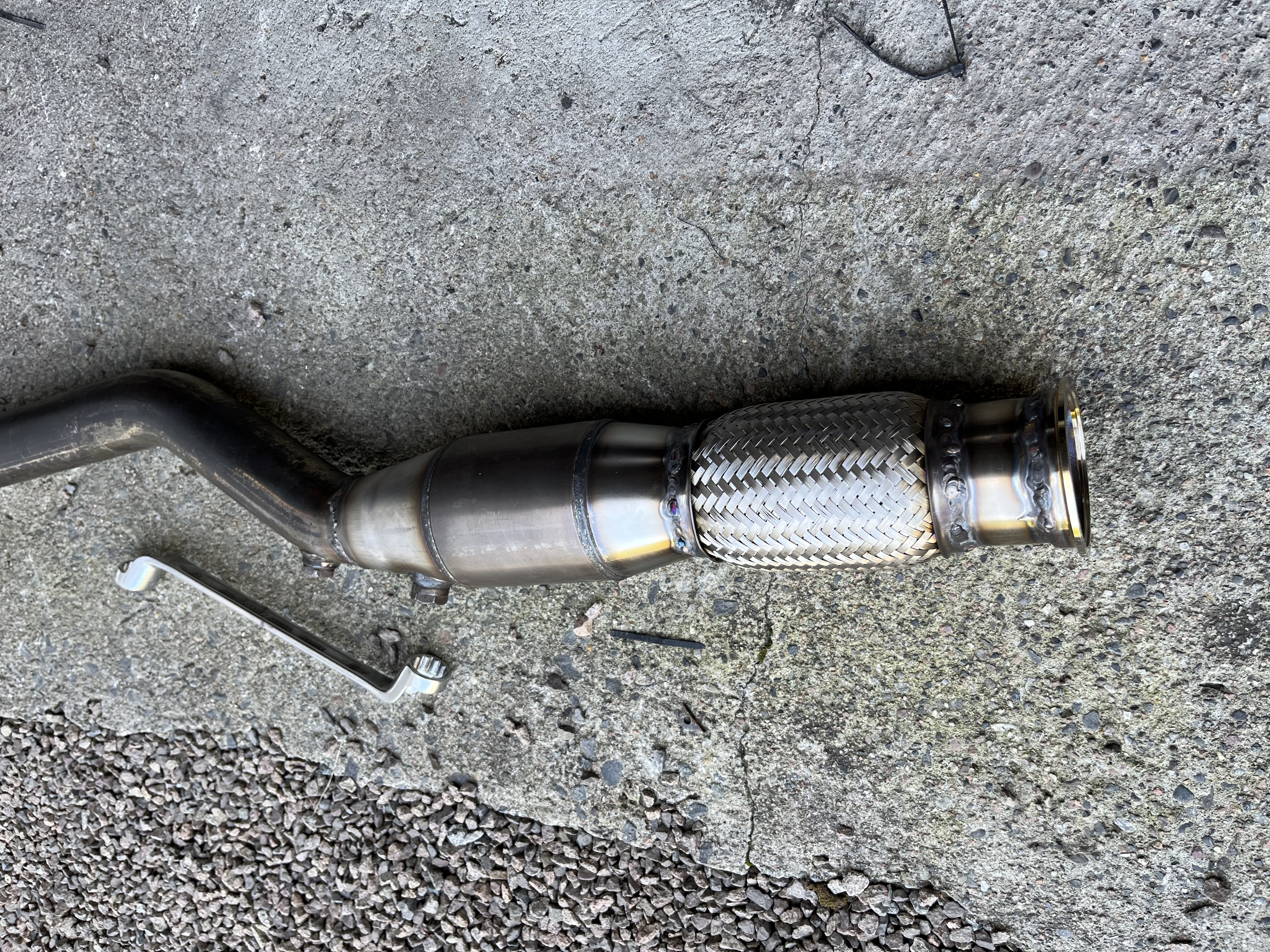
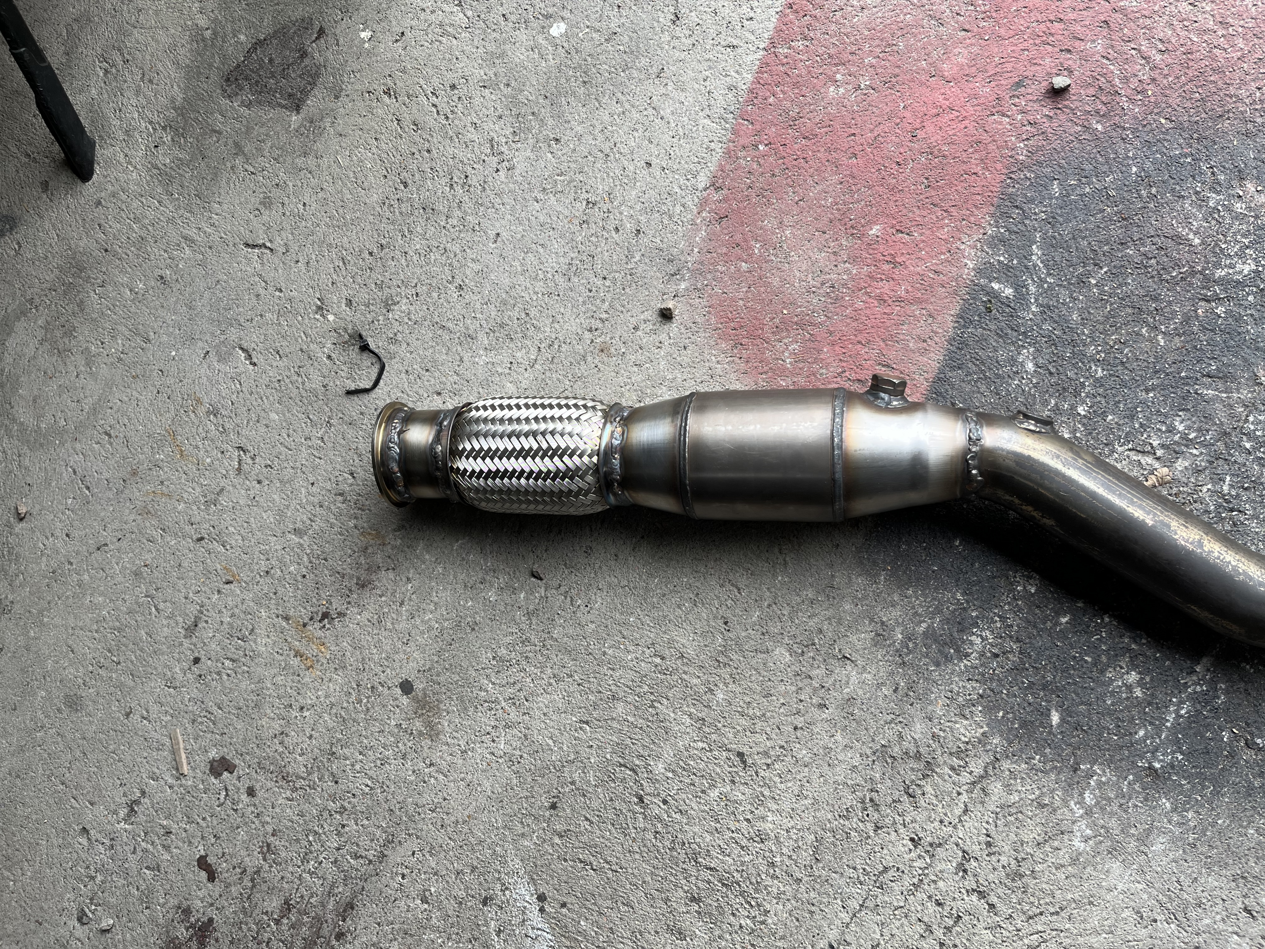
For exhaust I ended up using my 2.5” GWR but with a custom 3” flex and race CAT. Had plans to just use the midpipe adaption kit that Fab9 sells but turns out it’s discontinued.
To make this as hard as possible I decided to learn TIG welding. How hard can it be right…. it’s HARD.
TIG welding stainless is like learing to ride a bike and how to swim at the same time. Takes a lot of patience, setup knowledge, cleaning and many hours failing. But when perfect dabs of 316l perfectly gets sucked into the shielded weld pool with decent HAZ it’s worth it!
After like 50 youtube videos, 10l of argon, and too little practice I managed to patch toghether the parts with grey turd welds.
It’s still holding up fine.
 |
 |
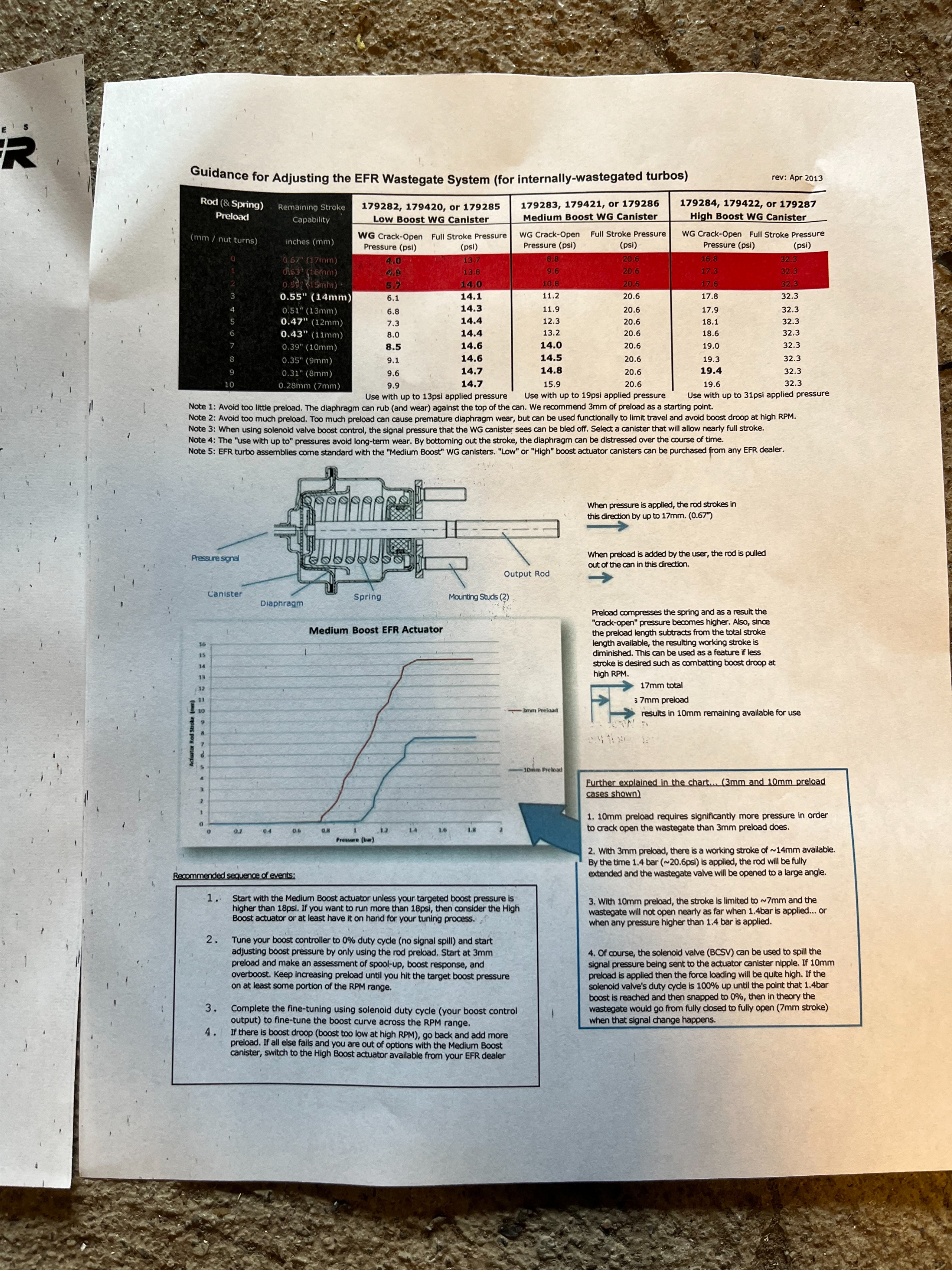
First driving impression is: WOW.. very little in this world can put a grin on my face like a turbo charged engine that transitions into boost. To not ruin this project at birth I’m running very conservative timing/boost of 16deg @ 0.6 bar / ~9 psi on spring pressure. I adjusted the arm with minimum preload according the the EFR instructions. I had expected more but 0.6 is perfect for base tuning.
But after like the 3rd full pull the clutch let go.. Just managed to adjust the VE in the ball park. Will have to do a full check of all piping and manifold during the winter as the VE dropped off a bit too steep in the 6300-7K range. The L5 is
Comments